Rockwell Automation Publication 6000-UM002E-EN-P - April 2018 119
Preventative Maintenance and Component Replacement Chapter 5
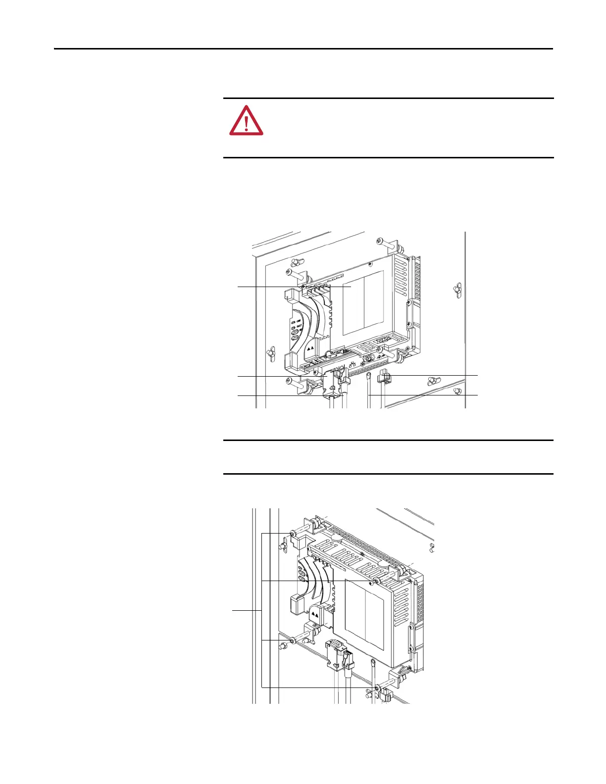
Replace the HMI
The touch screen is located on the LV Control cabinet door.
1. Disconnect the data cable from communication board, the EtherNet/IP
cable from PLC, the ground cable, and the 24V power supply cable.
2. Remove and retain four screws from HMI.
3. Install the new HMI from the inside of the LV Control cabinet door.
4. Reconnect all cables in reverse order of removal.
ATTENTION: Always perform Power Lockout procedure before servicing
equipment. Verify with a hot stick or appropriate voltage measuring device that
all circuits are voltage free. Failure to do so may result in severe burns, injury, or
death.
Data cable from
communication board
EtherNet/IP cable from PLC
Ground cable
24V power supply
HMI
Support the HMI from the outside of the door to prevent it from falling through
the front of the door.

 Loading...


