Rockwell Automation Publication 6000-UM002E-EN-P - April 2018 13
Introduction Chapter 1
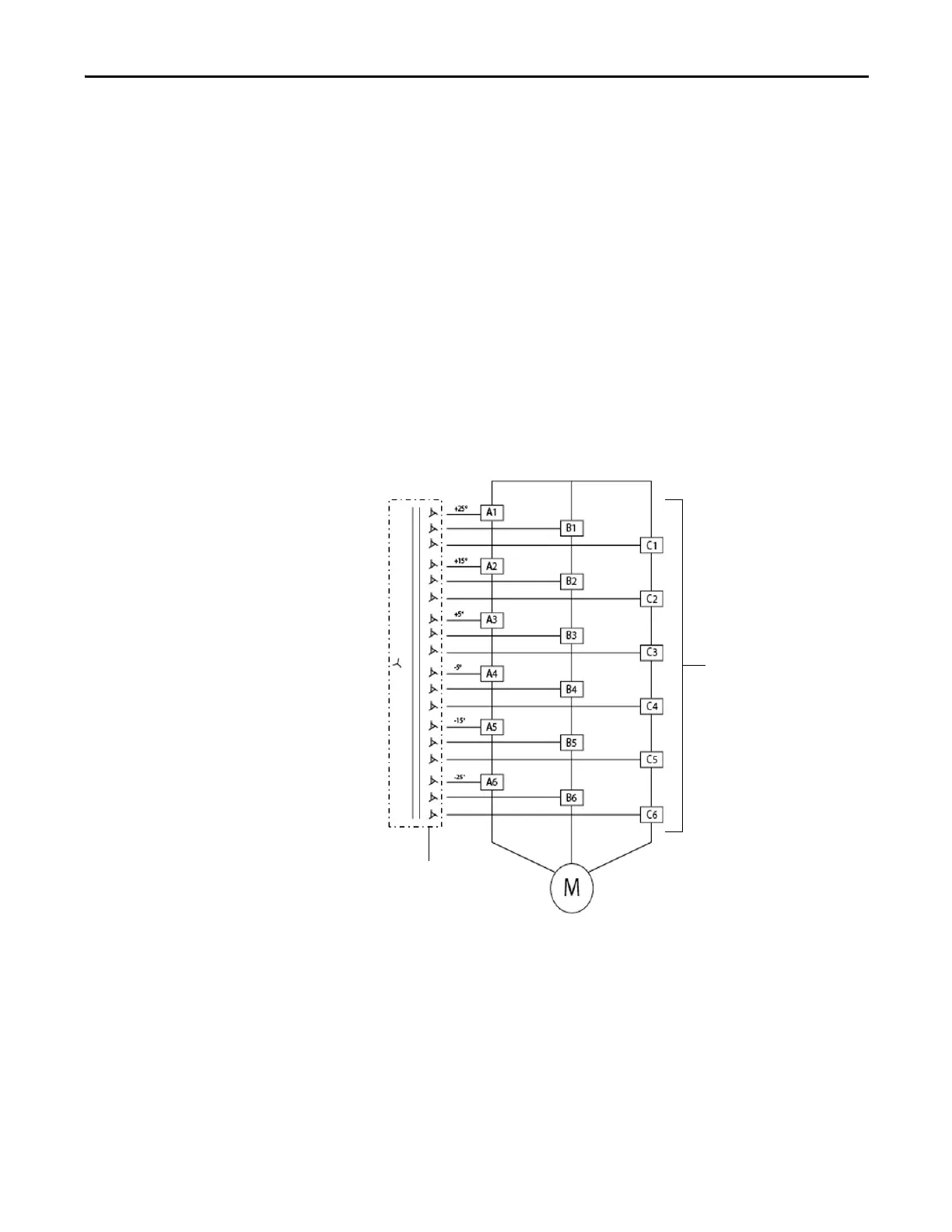
A number of identical low voltage power modules are series-connected
(cascaded) together to produce the medium voltage levels required to operate the
motor.
The voltage step for each module is relatively small and a Pulse Width
Modulation (PWM) switching pattern is used so output harmonics and torque
pulsations at the motor are minimal, even at lower speeds. This technology is
very motor friendly so standard motors can be used for new applications and it
also is ideal for retrofitting existing motors. This also allows for the motor cable
lengths required for most applications, without the requirement for output
filtering.
This power module concept makes maintenance quick and easy. Each module has
powerful built in diagnostics to identify and isolate a module needing
replacement, in the unlikely event of a failure. This minimizes power module
replacement time, so process uptime is maximized.
Figure 1 - 6.6 kV Example Power Structure
Input power
3-phase AC
Power Modules
Isolation
Transformer

 Loading...


