2-78 Digital Outputs
Digital Outputs Each drive provides digital (relay) outputs for external annunciation of a
variety of drive conditions. Each relay is a Form C (1 N.O. – 1 N.C. with
shared common) device whose contacts and associated terminals are rated
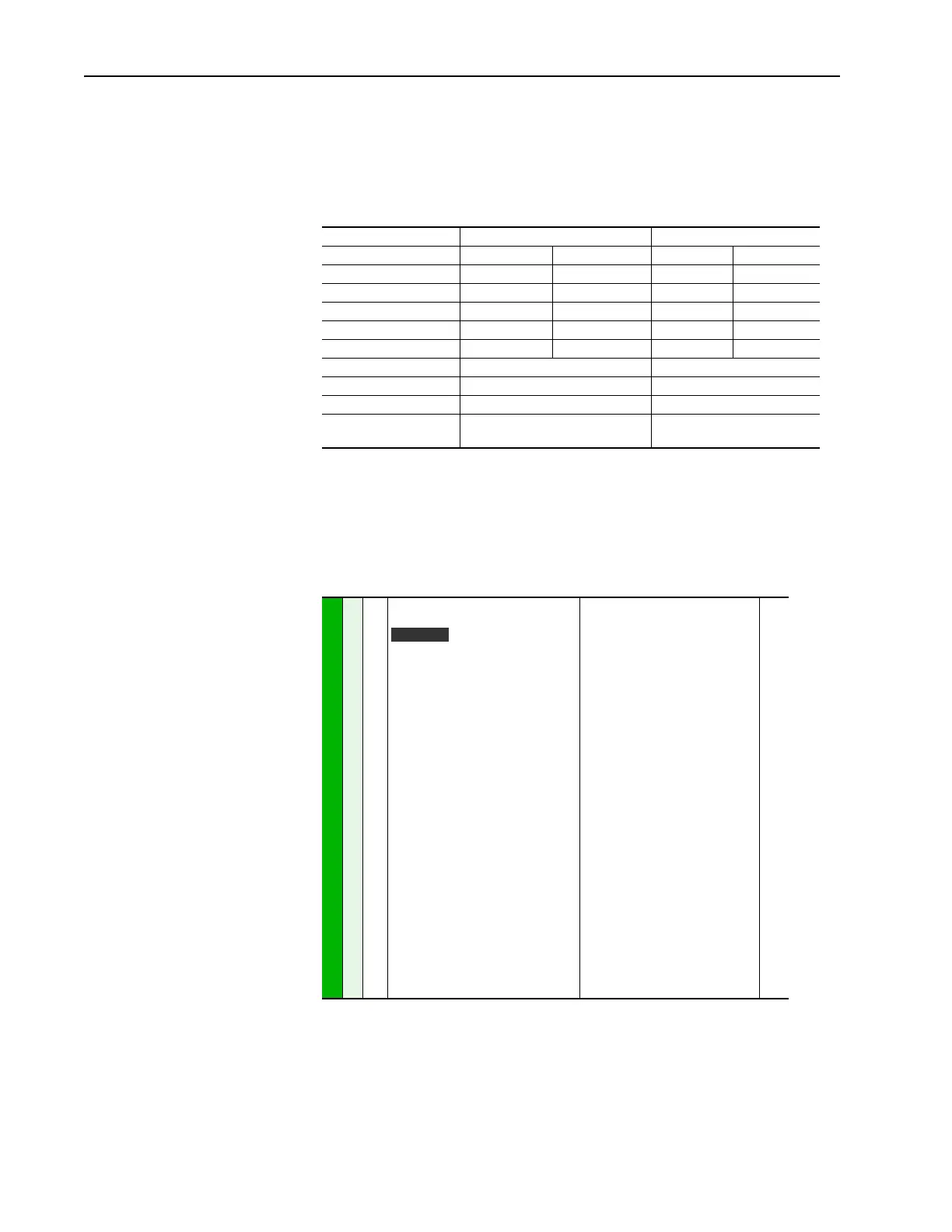
for a maximum of 250V AC or 220V DC. The table below shows
specifications and limits for each relay/contact.
Configuration
The outputs may be independently configured via the following parameters
to switch for various states of the drive.
PowerFlex 700 Digital Output Selection
PowerFlex 70 PowerFlex 700
Resistive Load Inductive Load Resistive Load Inductive Load
Rated Voltage 250V AC 250V AC 240V AC 240V AC
220V DC 220V DC 30V DC 30V DC
Maximum Current 3 A 1.5 A 5 A 3.5 A
Maximum Power AC - 50 VA AC - 25 VA 1200 VA 840 VA
DC - 60 W DC - 30 W 150W 105W
Minimum DC Current 10 µA10 mA
Switching Time 8 ms 10 ms
Initial State De-energized De-energized
Number of relays
(Standard I/O)
2 2 - Standard Control
3 - Vector Control
380
384
388
[Digital Out1 Sel]
(5)
[Digital Out2 Sel]
[Digital Out3 Sel]
Selects the drive status that will energize
a (CRx) output relay.
(1 )
Any relay programmed as Fault or
Alarm will energize (pick up) when
power is applied to drive and
deenergize (drop out) when a fault
or alarm exists. Relays selected for
other functions will energize only
when that condition exists and will
deenergize when condition is
removed.
(2)
Vector Control Option Only.
(3)
Activation level is defined in [Dig Outx
Level] below.
(4)
Vector firmware 3.001 and later.
(5)
When [TorqProve Cnfg] is set to
“Enable,” [Digital Out1 Sel] becomes
the brake control and any other
selection will be ignored.
(6)
Refer to Option Definitions in User
Manual.
Default:
Options:
1
4
4
1
2
3
4
5
6
7
8
9
10
11
12
13
14
15
16
17
18
19
20
21-26
27
28
29
30
“Fault”
“Run”
“Run”
“Fault”
(1)
“Alarm”
(1)
“Ready”
“Run”
“Forward Run”
“Reverse Run”
“Auto Restart”
“Powerup Run”
“At Speed”
(6)
“At Freq”
(3)
“At Current”
(3)
“At Torque”
(3)
“At Temp”
(3)
“At Bus Volts”
(3)
“At PI Error”
(3)
“DC Braking”
“Curr Limit”
“Economize”
“Motor Overld”
“Power Loss”
“Input 1-6 Link”
(6)
“PI Enable”
(2)
“PI Hold”
(2)
“Drive Overload”
(2)
“Param Cntl”
(4, 6)
381
385
389
382
386
390
383
002
001
003
004
218
012
137
157
147
053
048
184
379
Vector

 Loading...


