2-152 Reflected Wave
For example, % selected, Max Frequency = 130, Speed Reference = 22 Hz,
Trim Reference = 20%. 4.4 Hz will be added to the Speed Reference.
% not selected, Max Frequency = 130, Speed Reference = 22 Hz, Trim
Reference = 20%. 26 Hz will be added to the Speed Reference.
Reflected Wave [Compensation]
The pulses from a Pulse Width Modulation (PWM) inverter using IGBTs
are very short in duration (50 nanoseconds to 1 millisecond). These short
pulse times combined with the fast rise times (50 to 400 nanoseconds) of the
IGBT, will result in excessive over-voltage transients at the motor.
Voltages in excess of twice the DC bus voltage (650V DC nominal at 480V
input) will occur at the motor and can cause motor winding failure.
The patented reflected wave correction software in the PowerFlex 70/700
will reduce these over-voltage transients from a VFD to the motor. The
correction software modifies the PWM modulator to prevent PWM pulses
less than a minimum time from being applied to the motor. The minimum
time between PWM pulses is 10 microseconds. The modifications to the
PWM modulator limit the over-voltage transient to 2.25 per unit volts
line-to-line peak at 600 feet of cable.
400 V Line = 540V DC bus x 2.25 = 1215V
480 V Line = 650V DC bus x 2.25 = 1463V
600 V Line = 810V DC bus x 2.25 = 1823 V
The software is standard and requires no special parameters or settings.
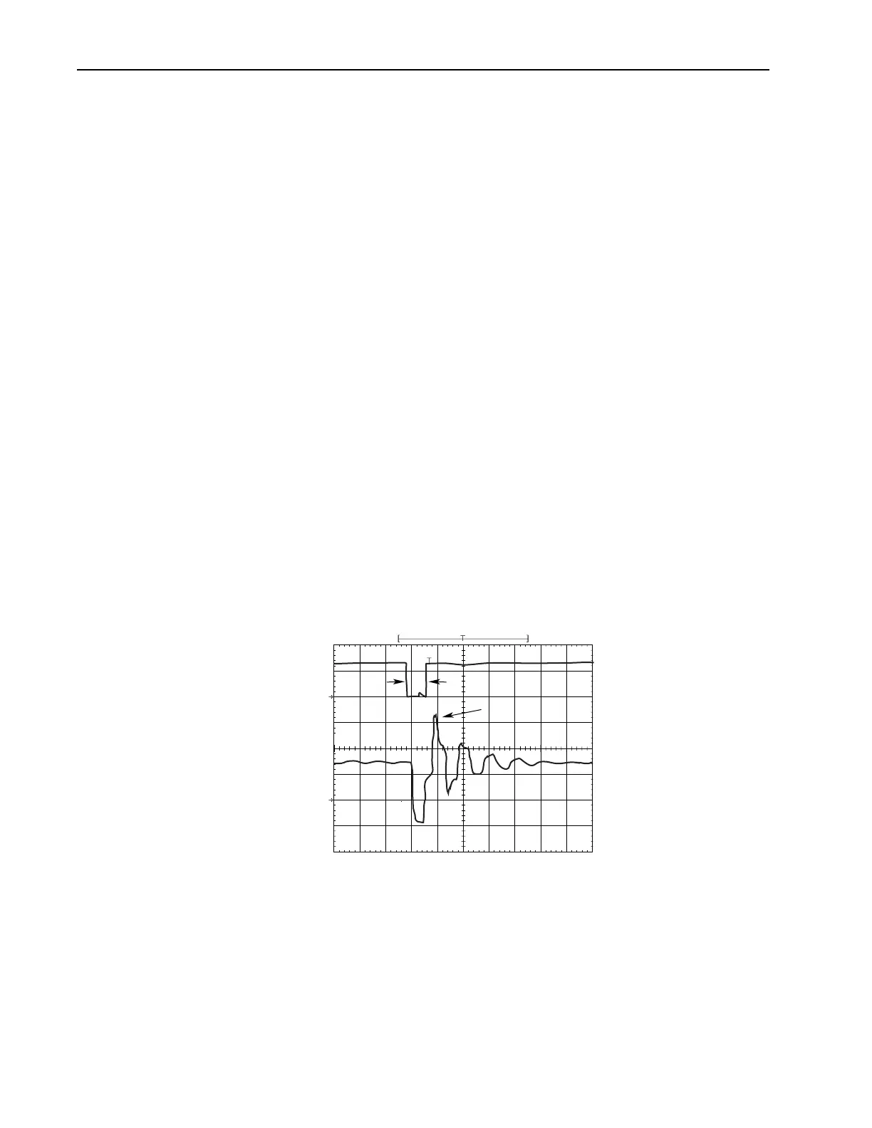
The above figure shows the inverter line-to-line output voltage (top trace)
and the motor line-to-line voltage (bottom trace) for a 10 HP, 460V AC
inverter, and an unloaded 10 HP AC induction motor at 60 Hz operation.
500 ft. of #12 AWG cable connects the drive to the motor.
<T
α
1670 V
pk
5010152025
Time (sec)
30 35 40 45 50
500
V/div
0
500
V/div
Inverter
Motor
0

 Loading...


