Stop Modes 2-201
Stop Modes [Stop Mode A, B]
[DC Brake Lvl Sel]
[DC Brake Level]
[DC Brake Time]
1. Coast to Stop - When in Coast to Stop, the drive acknowledges the Stop
command by shutting off the output transistors and releasing control of
the motor. The load/motor will coast or free spin until the mechanical
energy is dissipated.
2. Dynamic Braking is explained in detail in the PowerFlex Dynamic
Braking Selection Guide, presented in Appendix A
.
3. DC Brake is selected by setting [Stop Mode A] to a value of “3.” The
user can also select the amount of time the braking will be applied and
the magnitude of the current used for braking with [DC Brake Time] and
[DC Brake Level]. This mode of braking will generate up to 40% of
rated motor torque for braking and is typically used for low inertia loads.
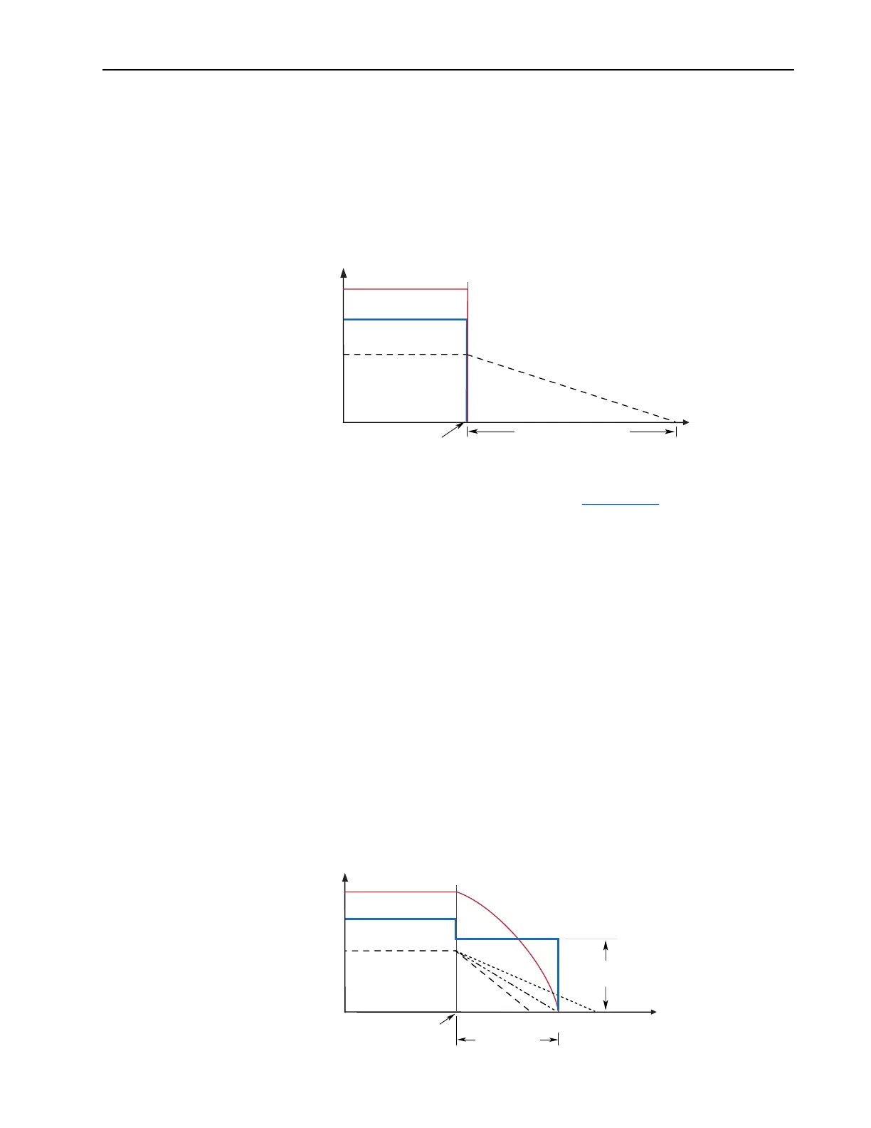
When in Brake to Stop, the drive acknowledges the Stop command by
immediately stopping the output and then applying a programmable DC
voltage [DC Brake Level] to 1 phase of the motor.
The voltage is applied for the time programmed in [DC Brake Time].
After this time has expired, all output ceases. If the load is not stopped, it
will continue to coast until all energy is depleted (A on the diagram
below). If the time programmed exceeds the needed time to stop, the
drive will continue to apply the DC hold voltage to the non-rotating
motor (B on the diagram below). Excess motor current could cause
motor damage. The user is also cautioned that motor voltage can exist
long after the Stop command is issued. The right combination of Brake
Level and Brake Time must be determined to provide the safest, most
efficient stop (C on the diagram below).
Coast Time is load dependent
Stop
Command
Time
Output Voltage
Output Current
Motor Speed
Stop
Command
DC Hold Time
(A)(C)(B)
Time
Output Voltage
Output Current
Motor Speed
DC
Hold Level

 Loading...


