2-114 Masks
Masks A mask is a parameter that contains one bit for each of the possible
Adapters. Each bit acts like a valve for issued commands. Closing the valve
(setting a bit's value to 0) stops the command from reaching the drive logic.
Opening the valve (setting a bit's value to 1) allows the command to pass
through the mask into the drive logic.
Example: A customer's process is normally controlled by a remote PLC,
but the drive is mounted on the machine. The customer does not want
anyone to walk up to the drive and reverse the motor because it would
damage the process. The local HIM (drive mounted Adapter 1) is
configured with an operator's panel that includes a “REV” Button. To assure
that only the PLC (connected to Adapter 2) has direction control, the
[Direction Mask] can be set as follows:
276 [Logic Mask]
Determines which adapters can control the drive. If the bit for an adapter is set to
“0,” the adapter will have no control functions except for stop.
288
thru
297
277 [Start Mask]
Controls which adapters can issue start
commands.
See [Logic Mask]
. 288
thru
297
278 [Jog Mask]
Controls which adapters can issue jog
commands.
See [Logic Mask]
. 288
thru
297
COMMUNICATION
Masks & Owners
279 [Direction Mask]
Controls which adapters can issue
forward/reverse direction commands.
See [Logic Mask]
. 288
thru
297
280 [Reference Mask]
Controls which adapters can select an
alternate reference; [Speed Ref A, B Sel]
or [Preset Speed 1-7].
See [Logic Mask]
. 288
thru
297
281 [Accel Mask]
Controls which adapters can select
[Accel Time 1, 2].
See [Logic Mask]
. 288
thru
297
282 [Decel Mask]
Controls which adapters can select
[Decel Time 1, 2].
See [Logic Mask]
. 288
thru
297
283 [Fault Clr Mask]
Controls which adapters can clear a fault.
See [Logic Mask]
. 288
thru
297
284 [MOP Mask]
Controls which adapters can issue MOP
commands to the drive.
See [Logic Mask]
. 288
thru
297
285 [Local Mask]
Controls which adapters are allowed to
take exclusive control of drive logic
commands (except stop). Exclusive
“local” control can only be taken while the
drive is stopped.
See [Logic Mask]
. 288
thru
297
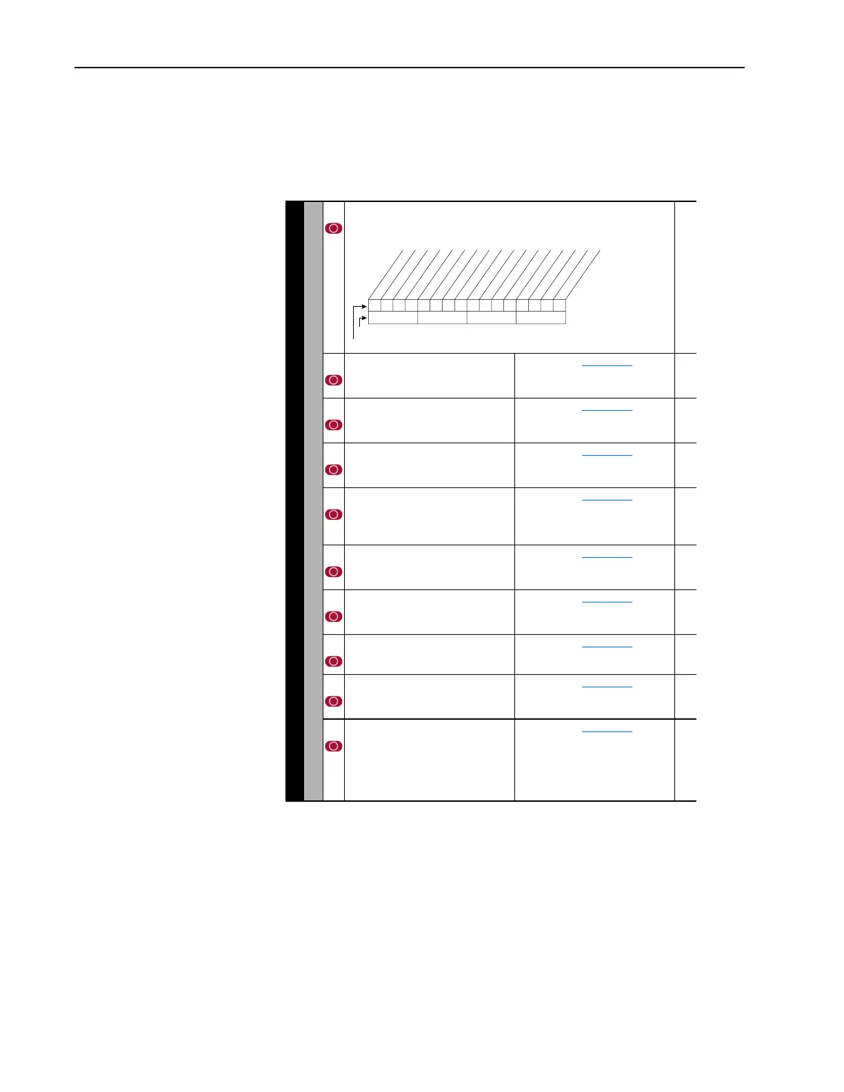
111111xxxxxxxxxx
10 01234567891112131415
1 = Control Permitted
0 = Control Masked
x = Reserved
Bit #
Factory Default Bit Values
Digital In
DPI Port 1
DPI Port 2
DPI Port 3
DPI Port 4
DPI Port 5

 Loading...


