10 Rockwell Automation Publication 20A-IN009E-EN-P - January 2015
PowerFlex 70 Adjustable Frequency AC Drive
Table 1 - PowerFlex 70 EN61800-3 EMC Compatibility
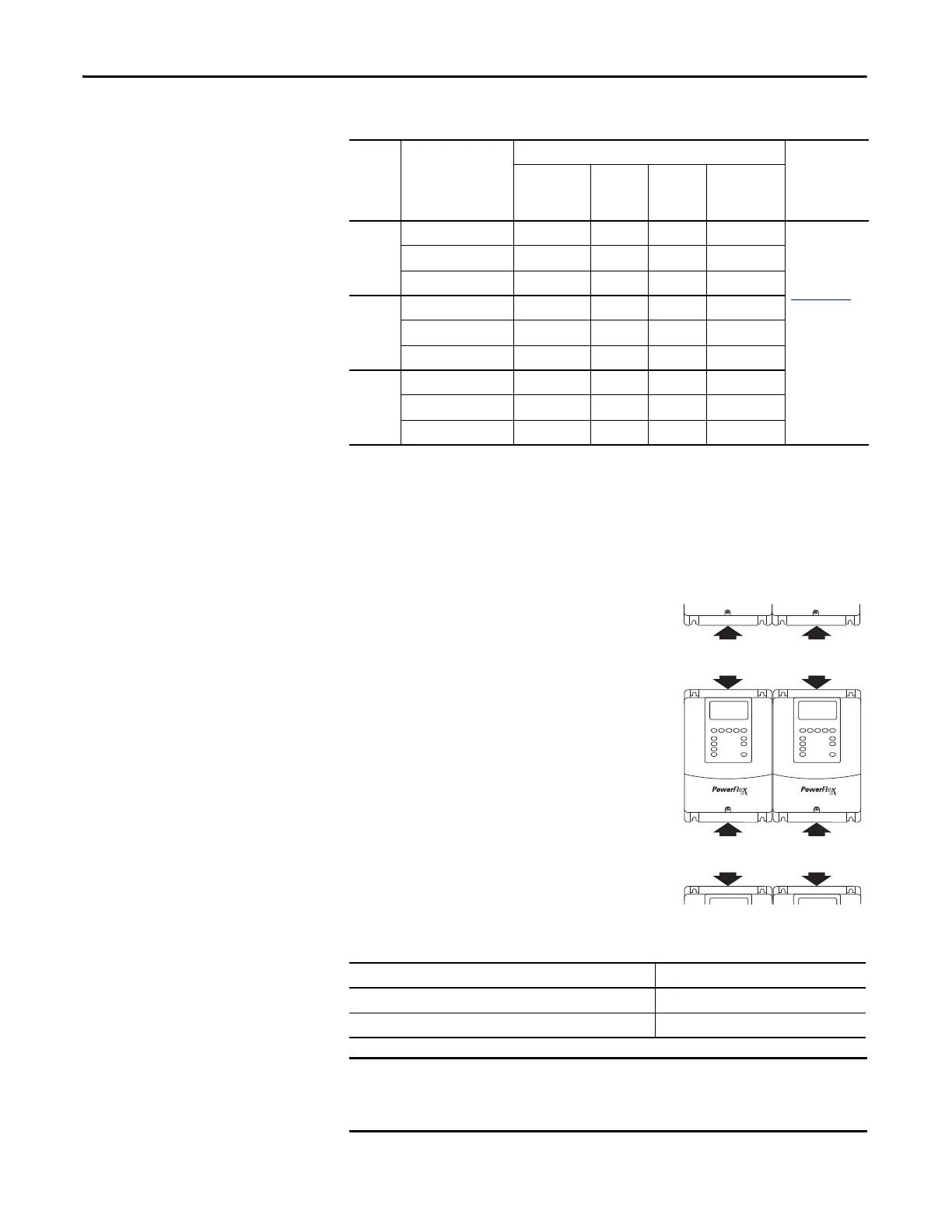
Step 2: Mount the Drive –
Minimum Requirements
This section describes the minimum requirements to mount the drive.
Minimum Mounting Clearances
Specified vertical clearance requirements are
intended to be from the drive to the closest
object that can restrict airflow through the drive
heat sink and chassis. The drive must be
mounted in a vertical orientation as shown, and
must make full contact with the mounting
surface. Do not use standoffs or spacers. In
addition, inlet air temperature must not exceed
the product specification.
Maximum Surrounding Air Temperature
Frame Drive Description
Second Environment
First
Environment
Restricted
Distribution
Restrict Motor
Cable to 40 m
(131 ft)
Internal
Filter
Option
External
Filter
Input Ferrite
(1)
(1) Input cables through a Ferrite Core (frames A, B, and C Fair-Rite #2643102002 or equivalent, frames D and E Fair-Rite #2643251002
or equivalent).
A Drive only X X See PowerFlex
Reference
Manual,
publication
PFLEX-RM001
With any comm option X X
With remote I/O X X X
BDrive only X X
With any comm option X X
With remote I/O X X X
C, D, E Drive only X
With any comm option X
With remote I/O X X
Enclosure Rating Temperature Range
Open Type, IP 20, NEMA/UL Type 1 and flange mount 0…50 °C (32…122 °F)
IP54 and IP66 NEMA/UL Type 4X/12 0…40 °C (32…104 °F)
ATTENTION: Some drives are equipped with an adhesive label on the top of
the chassis. Removing the adhesive label from the drive changes the NEMA/
UL enclosure rating from Type 1 Enclosed to Open Type.
76.2 mm
(3.0 in.)
76.2 mm
(3.0 in.)
76.2 mm
(3.0 in.)
76.2 mm
(3.0 in.)

 Loading...


