Rockwell Automation Publication 20A-IN009E-EN-P - January 2015 39
PowerFlex 70 Adjustable Frequency AC Drive
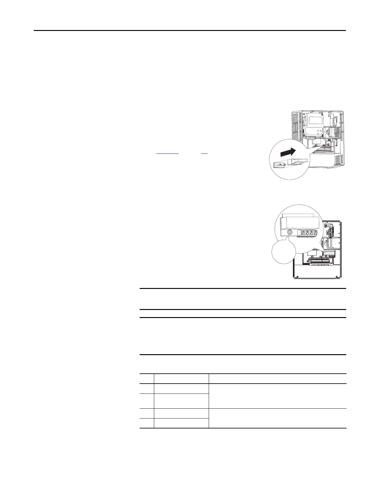
Hardware Enable Circuitry (Only Enhanced Control)
By default, you can program a digital input as an enable input. The status of this
input is interpreted by drive software. If the application requires the drive to be
disabled without software interpretation, a hardware enable configuration is
used. To use the hardware enable configuration, remove the enable jumper
(ENBL JMP) and connect the enable input to Digital In 6 (see below).
1. Remove the drive cover.
2. Locate and remove the enable jumper on
the main control board (see the diagram).
3. Connect the enable to Digital In 6 (see
Tab l e 1 7
on page 36).
Safe Torque Off Board Option (Only Enhanced Control)
The optional PowerFlex Safe Torque Off board,
when used with suitable safety components,
provides protection according to EN 954-1:1997;
Category 3 for safe off and protection against
restart. The PowerFlex safe off option is just one
safety control system. All components in the
system must be chosen and applied correctly, to
achieve the desired level of operator safeguarding.
Table 18 - Terminal Description
The drive enable digital input is a solid-state circuit. The safety outputs on the
safety module must not be configured for pulsed/safety pulse test.
The drive ships with the hardware enable jumper (ENBL JMP) installed. You
must remove the jumper if you are using the DriveGuard® Safe Torque Off
option. If you do not remove the jumper, the drive faults when a start
command is issued.
No. Signal Description
1 Monitor - N.C. Normally closed contacts for monitoring relay status.
Maximum Resistive Load: 250V AC / 30V DC / 50 VA / 60 W
Maximum Inductive Load: 250V AC / 30V DC / 25 VA / 30 W
2 Common - N.C.
3 +24V DC Connections for user supplied power to energize coil.
4 24V Common
1234
0.8…1.1 N•m
(7…10 lb•in)
20A-DG01

 Loading...


