Rockwell Automation Publication 20A-IN009E-EN-P - January 2015 29
PowerFlex 70 Adjustable Frequency AC Drive
Disconnecting MOVs and Common Mode Capacitors
Before proceeding, be sure that all power to the drive has been removed.
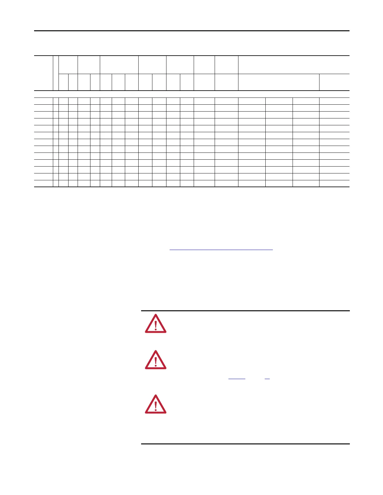
Table 13 - 600 Volt AC Single-phase Input Drive Ratings and Input Protection Devices
Cat. No.
Frame
(1)
Hp
Rating
Input
Ratings Output Amps
Dual
Element Time
Delay Fuse
Non-time
Delay Fuse
Circuit
Breaker
(4)
Motor
Circuit
Protector
(6)
140M Motor Protector with Adjustable Current Range
(7)
(8)
ND HD Amps kVA Cont. 1 Min. 3 Sec. Min
(2)
Max
(3)
Min
(2)
Max
(3)
Max
(5)
Max
(5)
Available Catalog Numbers
(9)
Minimum
Enclosure Volume
(in.
3
)
(10)
600 Volt AC Input
20AE0P9 A 0.5 0.33 1.3 0.7 0.5 0.6 0.7 3 3 3 3.5 15 3 140M-C2E-B16 – – 3441
20AE1P7 A 1 0.75 1.9 1 0.9 1 1.3 3 6 3 6 15 3 140M-C2E-B25 140M-D8E-B25 – 3441
20AE2P7 A 2 1.5 3 1.6 1.4 1.8 2.4 4 6 4 10 15 7 140M-C2E-B40 140M-D8E-B40 – 3441
20AE3P9 B 3 2 4.4 2.3 2 2.2 3 6 8 6 15 15 7 – 140M-D8E-B63 – 3441
20AE6P1 B 5 3 7.5 3.9 3.1 3.4 4.6 10 12 10 20 20 15 – 140M-D8E-C10 140M-F8E-C10 3441
20AE9P0 C 7.5 5 7.7 4 4.5 5 6.8 10 20 10 35 35 15 – 140M-D8E-C10 140M-F8E-C10 3441
20AE011 C 10 7.5 9.8 5.1 5.5 6.8 9 15 20 15 40 40 15 – 140M-D8E-C16 140M-F8E-C16 3441
20AE017 D 15 10 15.3 8 8.5 9.4 12.8 20 35 20 60 60 30 – – 140M-F8E-C20 5098
20AE022 D 20 15 20 10.4 11 12.8 17 25 45 25 80 80 30 – – 140M-F8E-C25 5098
20AE027 D 25 20 24.8 12.9 13.5 16.5 22 35 60 35 100 100 50 – – 140M-F8E-C25 5098
20AE032 D 30 25 29.4 15.3 16 20.3 27 40 70 40 125 125 50 – – 140M-F8E-C32 5098
20AE041 E 40 30 37.6 19.6 20.5 24 32 50 90 50 150 150 100 – – – –
20AE052 E 50 40 47.7 24.8 26 30.8 41 60 110 60 200 200 100 – – – –
(1) For IP 66 (NEMA/UL Type 4X/12) enclosures, drives listed as Frame A increase to Frame B and drives that are listed as Frame C increase to Frame D.
(2) Minimum protection device size is the lowest rated device that supplies maximum protection without nuisance tripping.
(3) Maximum protection device size is the highest rated device that supplies drive protection. For US NEC, minimum size is 125% of motor FLA. Ratings that are shown are maximum.
(4) Circuit Breaker - inverse time breaker. For US NEC, minimum size is 125% of motor FLA. Ratings that are shown are maximum.
(5) Maximum allowable rating by US NEC. Exact size must be chosen for each installation.
(6) Motor Circuit Protector - instantaneous trip circuit breaker. For US NEC, minimum size is 125% of motor FLA. Ratings that are shown are maximum.
(7) Bulletin 140M with adjustable current range must have the current trip set to the minimum range that the device will not trip.
(8) Manual Self-Protected (Type E) Combination Motor Controller, UL listed for 208 Wye or Delta, 240 Wye or Delta, 480Y/277 or 600Y/347. Not UL listed for use on 480V or 600V Delta/Delta, corner ground,
or high-resistance ground systems.
(9) The AIC ratings of the Bulletin 140M Motor Protector Circuit Breakers may vary. See Bulletin 140M Motor Protection Circuit Breakers Application Ratings
.
(10) When using a Manual Self-Protected (Type E) Combination Motor Controller, the drive must be installed in a ventilated or non-ventilated enclosure with the minimum volume specified in this column.
Application-specific thermal considerations may require a larger enclosure.
ATTENTION: Only qualified personnel familiar with adjustable frequency AC
drives and associated machinery can perform maintenance/repair of the
system. Failure to comply can result in personal injury and/or equipment
damage.
ATTENTION: To avoid an electric shock hazard, verify that the voltage on the
bus capacitors has discharged before performing any work on the drive.
Measure the DC bus voltage at the +DC and –DC terminals of the Power
Terminal Block (refer to Figure 9
on page 21 for location). The voltage must be
zero.
ATTENTION: The following information is merely a guide for proper
installation. Rockwell Automation cannot assume responsibility for the
compliance or the noncompliance to any code, national, local or otherwise for
the proper installation of this drive or associated equipment. A hazard of
personal injury and/or equipment damage exists if codes are ignored during
installation.

 Loading...


