20 Rockwell Automation Publication 20A-IN009E-EN-P - January 2015
PowerFlex 70 Adjustable Frequency AC Drive
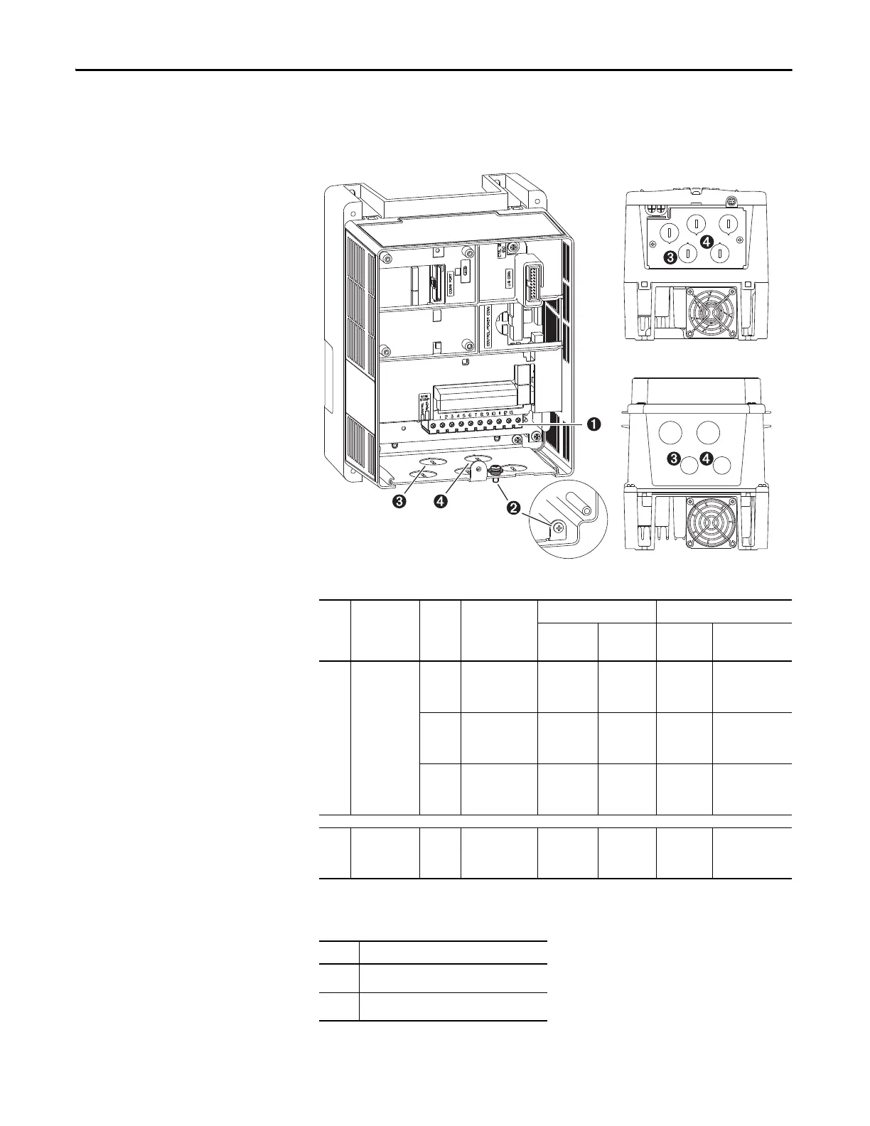
Power Terminal Block
Figure 8 - Typical Power Terminal Block Location (B frame shown)
Table 5 - Power Terminal Block Specifications
Table 6 - Wire Routing Recommendations
No. Name Frame Description
Wire Size Range
(1)
(1) Maximum/minimum sizes that the terminal block can accept – these are not recommendations.
Torque
Max
mm
2
(AWG)
Min
mm
2
(AWG)
Max
N•m (lb•in)
Recommended
N•m (lb•in)
➊
Power
terminal block
A, B, C Input power and
motor
connections
4.0 (10) 0.3 (22) 1.1 (10) 0.8 (7)
DInput power and
motor
connections
10.0 (6) 0.8 (18) 1.7 (15) 1.4 (12)
EInput power and
motor
connections
25.0 (3) 2.5 (14) 2.71 (24) 2.71 (24)
➋
SHLD terminal All Terminating
point for wiring
shields
— — 1.6 (14) 1.6 (14)
No. Description
➌
Suggested entry for incoming line wiring.
➍
Suggested entry for motor wiring.
IP 20 (NEMA/UL Type 1)
IP 66 (NEMA/UL Type 4X/12)

 Loading...


