Rockwell Automation Publication 20A-IN009E-EN-P - January 2015 49
PowerFlex 70 Adjustable Frequency AC Drive
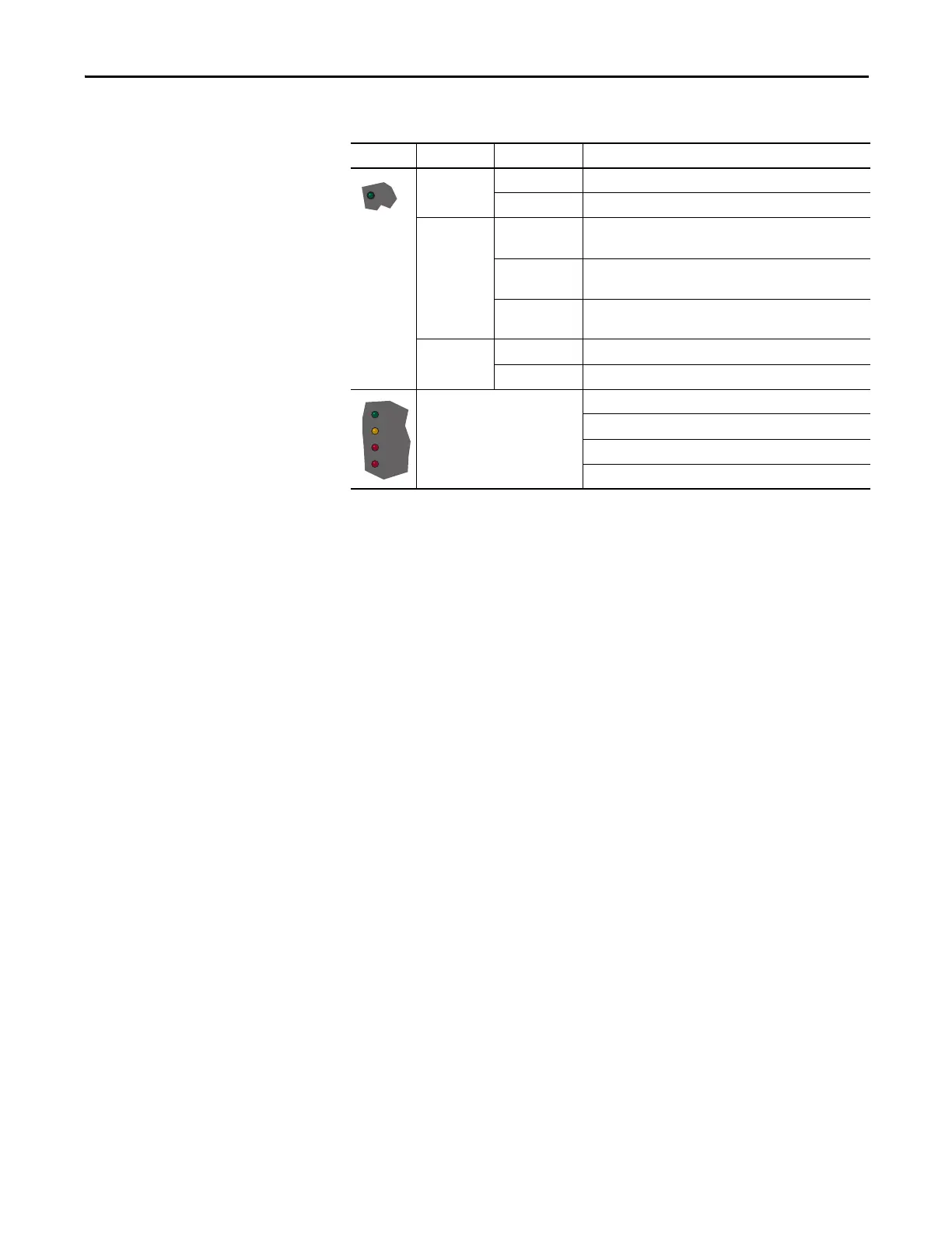
Drive Status Indicators
Common I/O Programming Changes
Your application needs can require changing parameters from their factory
default settings.
Speed Reference A
Change Speed Reference A from Analog In 2 to Analog In 1 to connect an
external potentiometer.
1. Set Parameter 090 [Speed Ref A Sel] to option 1, Analog In 1.
Sets the speed reference input to I/O terminals 14 and 15 for voltage, and
I/O terminals 16 and 17 for current.
2. Set Parameter 096 [TB Man Ref Sel] to option 9, MOP Level.
Eliminates a potential conflict alarm condition. Analog In 2 is not a valid
Speed Reference source if selected for any of the following parameters:
• 117 [Trim In Select]
• 126 [PI Reference Sel]
• 128 [PI Feedback Sel]
• 147 [Current Lmt Sel]
3. Set Parameter 091 [Speed Ref A Hi] to the upper value of the desired
speed reference range in Hz.
4. Set Parameter 092 [Speed Ref A Lo] to the lower value of the desired
speed reference range in Hz.
Speed Reference A is now configured for an external potentiometer.
Name Color State Description
Green Flashing The d rive is ready but is not running, and no faults are present.
Steady The drive is running and no faults are present.
Yellow Flashing,
drive stopped
An inhibit condition exists, the drive cannot be started. Check
parameter 214 [Start Inhibits].
Flashing,
drive running
An intermittent type 1 alarm condition exists.
Check parameter 211 [Drive Alarm 1].
Steady,
drive running
A continuous type 1 alarm condition exists.
Check parameter 211 [Drive Alarm 1].
Red Flashing A fault has occurred.
Steady A non-resettable fault has occurred.
See the communication adapter
user manual.
Status of DPI port internal communications (if present).
Status of communications module (when installed).
Status of network (if connected).
Status of secondary network (if connected).

 Loading...


