42 Rockwell Automation Publication 20A-IN009E-EN-P - January 2015
PowerFlex 70 Adjustable Frequency AC Drive
Step 5: Start-up Checklist
• This checklist supports the basic start-up menu option. See Start-up
Routines on page 47
for information on other start-up routines.
• A HIM is required to run the basic start-up routine.
• The basic start-up routine can modify parameter values for analog and
digital I/O. See Common I/O Programming Changes on page 49
.
Prepare For Drive Startup
1. Verify the input supply voltage.
2. Check the output wiring.
3. Check the control wiring.
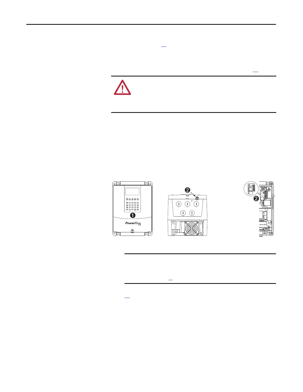
4. Connect a HIM to DPI Port 1 or 2.
Figure 15 - DPI Ports 1 and 2
5. Apply AC power and control voltages to the drive.
If the STS LED is not flashing green, see Drive Status Indicators on page
49
.
6. When prompted, select a display language.
The PowerFlex 70 start-up screen displays.
7. Press the enter key to display the start-up menu.
8. Use the arrow keys to highlight 2. Basic.
9. Press the enter key.
Use the enter key to follow the menu and step you through the start-up
routine.
ATTENTION: Power must be applied to the drive to perform the following
start-up procedure. Some of the voltages present are at incoming line potential.
To avoid electric shock hazard or damage to equipment, only qualified service
personnel can perform the following procedure. Thoroughly read and
understand the procedure before beginning.
If any of the six digital inputs are configured to Stop – CF (CF = Clear
Fault) or Enable, verify that signals are present or the drive cannot
start. See Troubleshooting – Abbreviated Fault and Alarm Listing on
page 50
for a list of potential digital input conflicts.
Optional Service
Connection Board
(SK-M9-SCB1)
provides temporary
DPI connection with
drive cover removed.

 Loading...


