Rockwell Automation Publication 750COM-UM009A-EN-P - May 2017 31
Configure the Interface Chapter 2
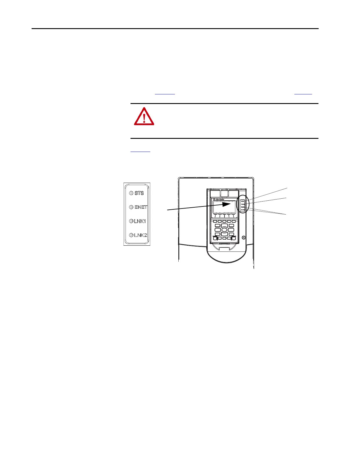
Start-up Status Indications
After power is applied, the drive STS (status) indicator and the built-in
EtherNet/IP interface ENET, LNK1, and LNK2 status indicators can be
monitored via status parameters, HIM status, and the software tool status, if
personal protective equipment is worn, they can also be viewed on the front of
the drive (Figure 6
). Possible start-up status indications are shown in Tab le 1.
Figure 6
is an example of a type of HIM available. Your HIM may appear
differently or in a different location.
Figure 6 - Drive and Interface Status Indicators
ATTENTION: Risk of injury or equipment damage exists. When a system is
configured for the first time, there can be unintended or incorrect machine
motion. Disconnect the motor from the machine or process during initial
system testing.

 Loading...


