56 Rockwell Automation Publication 750COM-UM009A-EN-P - May 2017
Chapter 3 Configuring the Drive in a Logix System
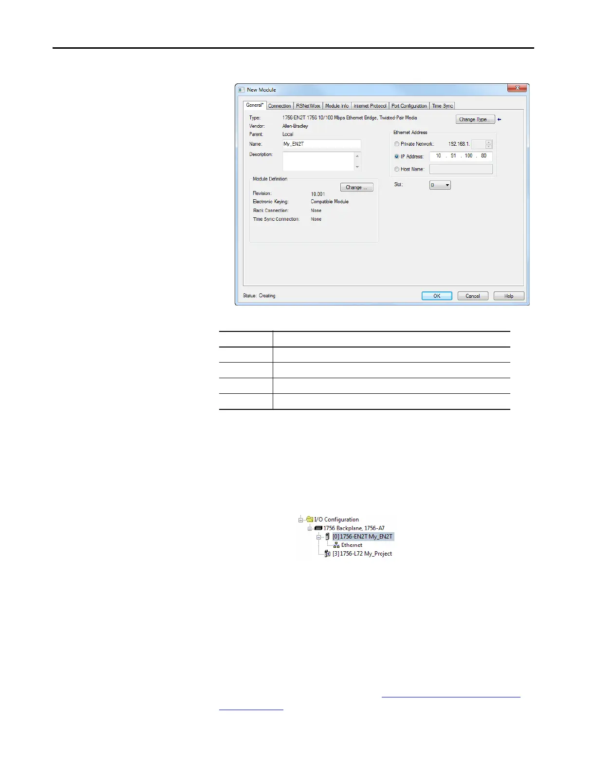
The New Module dialog box for the bridge appears.
7. Edit the following:
Click Change if you to edit the Revision, Electronic Keying, or other
features.
8. Click OK.
The bridge is now configured for the EtherNet/IP network, added to
the Logix Designer application project, and appears in the I/O
Configuration folder.
In our example, a 1756-EN2T bridge appears under the I/O
Configuration folder with its assigned name.
9. Click Close to close the Select Module Type window.
Add the Drive to the Project
To transmit data between the controller and the drive, you must add the drive
as a child device to the parent Ethernet bridge. In this example, Studio 5000
Logix Designer application software version 30 is used with PowerFlex 755T
Add-on Profile version 1.01. See section Updating the AOPs and Database
Files on page 63 to determine which AOP version you are currently using.
Box Setting
Name A name to identify the bridge.
Description Optional – description of the bridge.
Ethernet Address The address to use for the Ethernet bridge.
Slot The slot location in the chases where the Ethernet bridge resides.

 Loading...


