60 Rockwell Automation Publication 750COM-UM009A-EN-P - May 2017
Chapter 3 Configuring the Drive in a Logix System
4. Repeat for the Output tab and select the desired parameters to datalink.
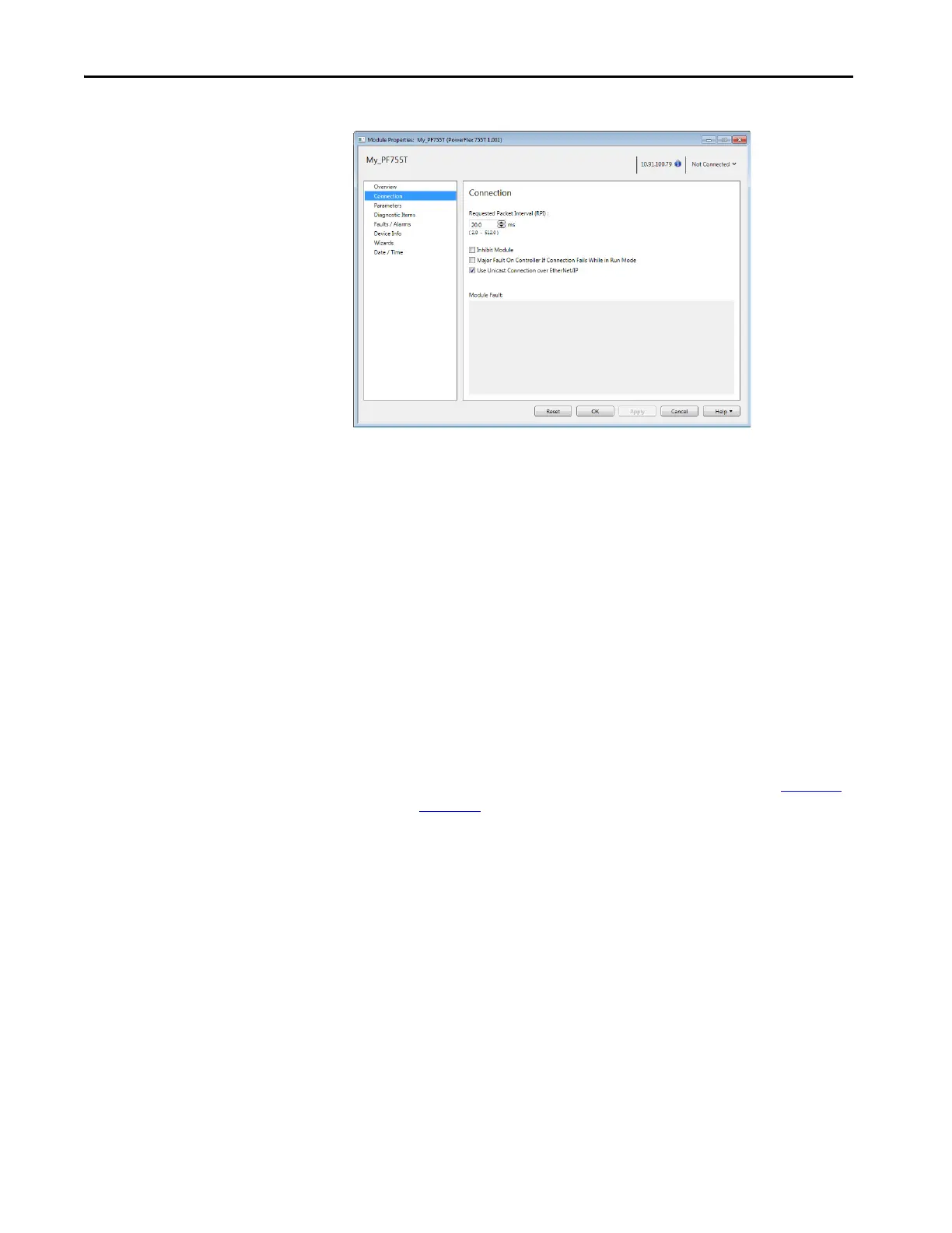
5. In the Requested Packet Interval (RPI) box, set the RPI to the desired
value (default is 20.0 milliseconds).
This value determines the interval that a controller uses to move data to
and from the drive. To conserve bandwidth, use higher values for
communicating with low priority devices.
The ‘Inhibit Module’ box, when checked, inhibits the controller from
communicating with the drive. When the ‘Major Fault On’ box is
checked, a major controller fault occurs when the connection to the
drive fails while the controller is in the Run mode.
Unicast reduces network traffic and is recommended whenever possible.
6. Click OK.
The new node now appears under the bridge in the I/O Configuration
folder. If you double-click the Controller Tags, you see that module-
defined data types and tags have been automatically created (Figure 10
and Figure 11
).
All tag names are defined and datalinks include the assigned drive
parameter name. After you save and download the configuration, these
tags allow you to access the Input and Output data of the drive via the
ladder logic of the controller.

 Loading...


