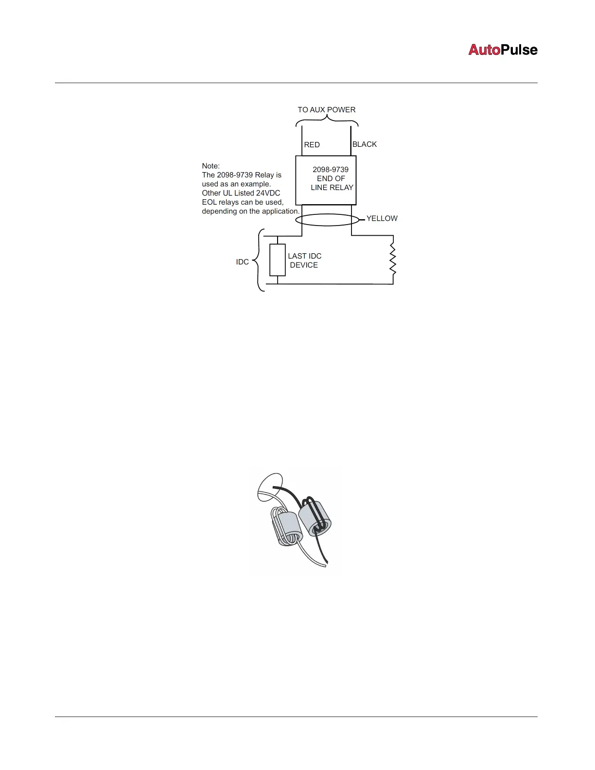
Figure 9: EOL relay diagram
• In areas of high lightning activity, or in areas that have large power surges, use the 2081-9044 Transient Suppressor on monitor
points.
• Do not run wires through elevator shafts.
• Only system wiring can be run together in the same conduit. When powering remote units using relay contacts, power for these
circuits must be provided by a PL power supply listed for fire-protective signaling use. An end-of-line (EOL) relay must be used to
supervise the Aux power circuit.
• Connect the output of the EOL relay to cause a trouble. Wire in series with the EOL resistor on an available initiating device circuit
(IDC) or individual addressable module (IAM).
3.3.1 Safety ground/ ferrite bead
Proper operation and protection against transient energy in accordance with UL 864 and ULC-S527 require the connection of safety
ground wire to cabinet chassis. Connect the safety ground before wiring any other circuits to the panel.
In addition, ferrite beads must be attached to the incoming AC power line as shown in Figure 10. Wrap the line leg twice through a ferrite
bead, and the neutral leg of the power line twice through the other ferrite bead.
Figure 10: Safety ground and ferrite bead
Note: The ferrite bead should be installed as close as possible to where power enters the panel.
page 12 579-1102AR Rev C
Z-20 Agent Releasing Panel Installation Manual
 Loading...