4.3.3 Class A wiring
Note: The Class A wiring style is set up in the programmer. Refer to the AUTOPULSE Z-20 Programmer’s Manual (579-1167AR), for more
information.
To connect the power supply to reverse-polarity, non-addressable notification appliances using Class A wiring, complete the following
steps:
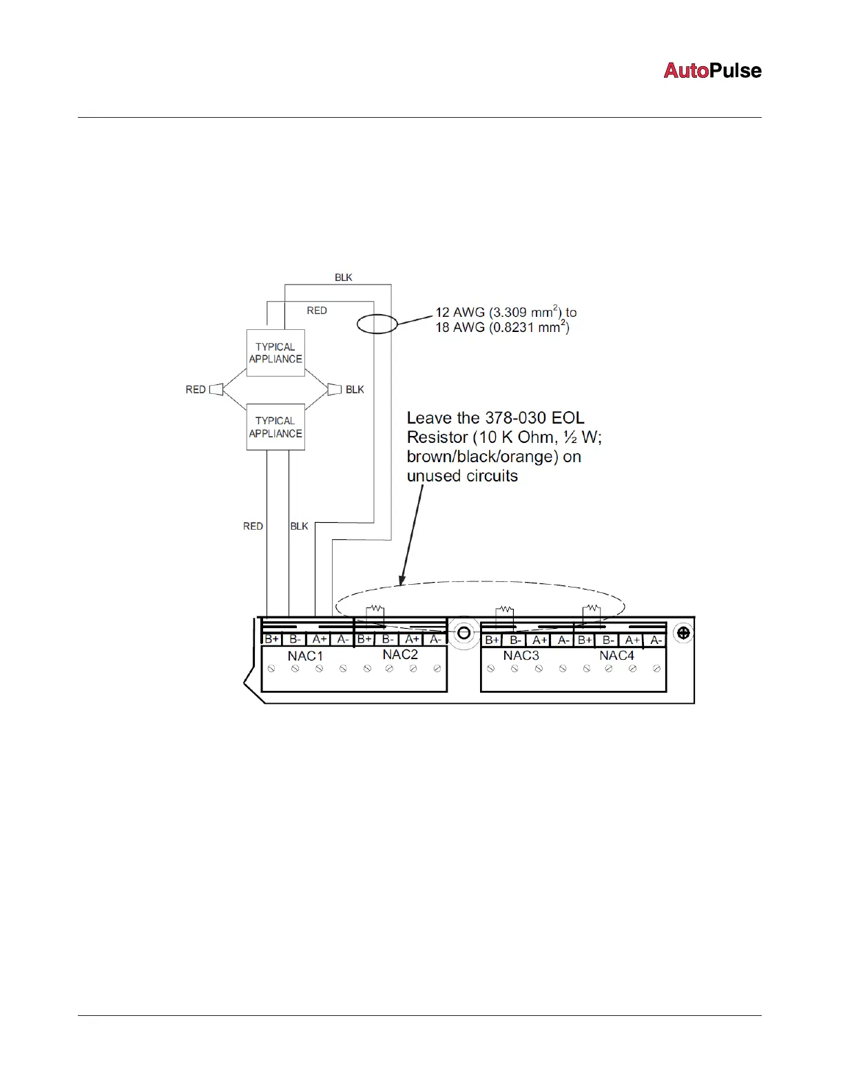
1. Route wire from the B+ and B- outputs of the power supply to the appropriate inputs on a peripheral notification appliance. Use
NAC1, NAC2, NAC3, or NAC4, see Figure 14.
2. Route the wire from the first appliance to the next. Repeat this for each appliance.
Figure 14: Class A NAC wiring
3. Route the wire from the last appliance to the A+ and A- inputs on the same NAC circuit of the power supply.
4. Repeat steps 1 through 3 for each NAC output you want to use.
5. Leave the 10 KOhms, 1/2 W, brown/black/orange resistor (378-030) on each unused circuit. Circuits in use do not require an
external end-of-line resistor.
page 19 579-1102AR Rev C
Z-20 Agent Releasing Panel Installation Manual
 Loading...