4.3.4 Class B wiring
Note: The Class B wiring style is set up in the programmer. Refer to the AUTOPULSE Z-20 Programmer’s Manual (579-1167AR) for more
information.
To connect the power supply to appliances using Class B wiring, complete the following steps:
1. Route the wire from the B+, B- outputs on TB2 and TB3 of the power supply to the appropriate inputs on a peripheral notification
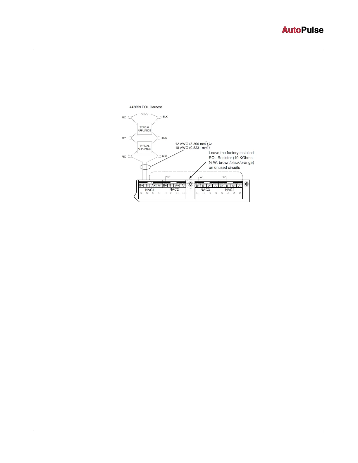
appliance. Use NAC1, NAC2, NAC3, or NAC4. See Figure 15.
Figure 15: Class B NAC wiring
2. Route the wire from the first appliance to the next. T-tapping is not permitted. Repeat this for each appliance.
3. Route the wire from the last appliance to the EOLR harness (10 kOhms, 1/2 W: P/N 733-894).
4. Repeat steps 1 through 3 for each NAC output you want to use.
5. Leave the factory installed EOL resistor (10 kOhms*, 1/2 W; brown/black/orange) on each unused circuit. The circuit must
connect B+ to B- terminals.
6. Document the EOL value in the panel for each circuit.
*Keep the original value and set the programmer accordingly.
page 20 579-1102AR Rev C
Z-20 Agent Releasing Panel Installation Manual
 Loading...