5.2.5 Class B Wiring
When wiring the circuit as Class B, both the B+, B- and A+, A- terminals are available for parallel connections. Within the IDNet circuitry, A+
is connected to B+, and A- is connected to B- so circuits can stem from either one. Additionally, two wires can be connected to each screw
terminal.
To wire an IDNet as a Class B circuit, complete the following steps:
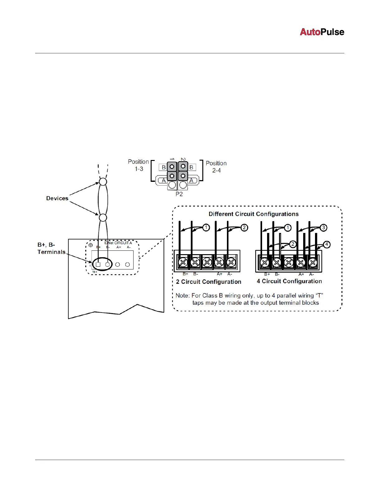
1. Set the jumpers on P2 to positions 1-3 and 2-4.
2. Route the wiring from the IDNet circuit primary terminals (B+, B-) to the corresponding inputs on the first device. It is possible to
add up to 4 circuits on the terminal block when using Class B wiring. See Figure 20 for the diagram.
3. Route the wiring from the first device to the next as in/out, see Figure 20. Repeat this for each device.
4. Shielded wire is not recommended. If shielded wires are present, cut and tape off the shield at each end (in the panel and at the
last device in each run) in the panel to prevent it coming into contact with other components. The metallic continuity of the shield
must be maintained and insulated throughout the entire length of the cable.
Figure 20: IDNet Class B wiring
page 26 579-1102AR Rev C
Z-20 Agent Releasing Panel Installation Manual
 Loading...