5.4 RUI section
RUI overview
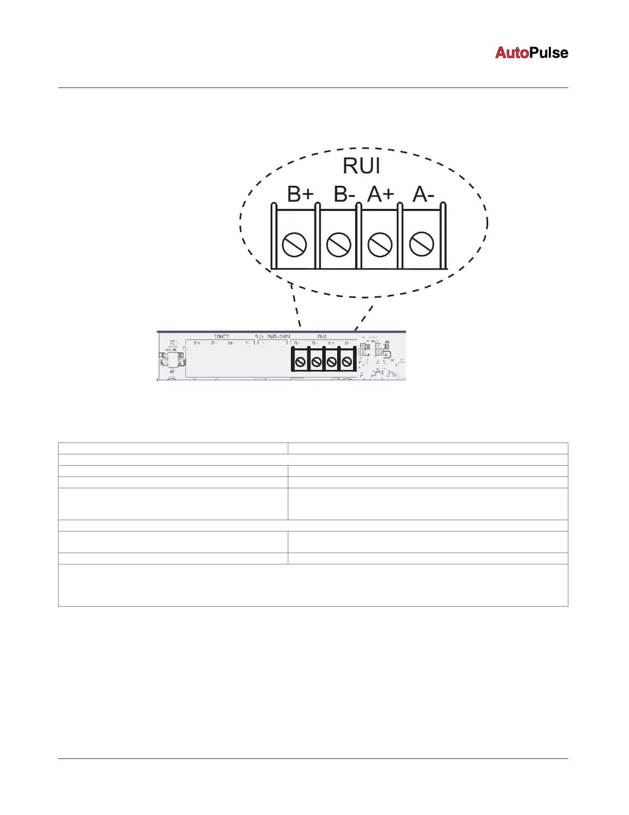
Wire from the power supply's RUI channel on terminal block TB1 to each RUI device. The wiring can be Class A or Class B.
Figure 23: Location of the RUI terminal block
See document 579-1172 for more information about the AUTOPULSE Z-20 Color Touchscreen LCD Remote Annunciator.
Table 19: RUI specifications
Supports: Up to 10 RUI devices.
Electrical specifications:
Channel voltage 29.5 V nominal.
Earth detection threshold 10K ohms minimum from either positive or negative terminals.
Capacitance The maximum allowed line-to-line capacitance (“+” to “-” terminals) is 0.58uF.
For applications with shielded wire, be sure that the total capacitance from
line-to-line plus the shield to either line is not more than 0.58uF.
Wiring
Maximum wiring distance:
(18 AWG, 16 AWG, 14 AWG, 12 AWG)
2,500 feet (762 m) to device from PSU card.
Maximum T- tapping length 10,000 feet (3,048 m).
Notes:
Maintain the correct polarity on terminal connections. Do not loop wires under terminals. If Class A is not used, configure jumpers P1
accordingly.
Shielded wire is not required. Twisted wire is recommended for improved noise immunity.
page 29 579-1102AR Rev C
Z-20 Agent Releasing Panel Installation Manual
 Loading...