5.2.3 Wiring parameters
Table 14 identifies the IDNet wiring parameters that you must consider when installing this card. For additional wiring information, see
Addressable Fire Alarm Panels Field Wiring Specifications (900-408).
Table 14: IDNet wiring parameters
IDNet wiring capacitance parameters
Parameter Value
Maximum supported channel capacitance The sum of line-to-line capacitance, plus the capacitance of either
line-to-shield (if shield is present) = 0.6 µF
IDNet wiring Class A, Class B and Class X limits
Channel loading Up to 125 devices 126 to 250 devices
Max. resistance to compatible devices. (Include the
2081-9044 Overvoltage Protector resistance when
applicable)
50 ohms maximum 35 ohms maximum
Maximum wiring distance*:
(18 AWG, 16 AWG, 14 AWG, 12 AWG)
4000 ft (1219 m) 2500 ft (762 m)
Note:
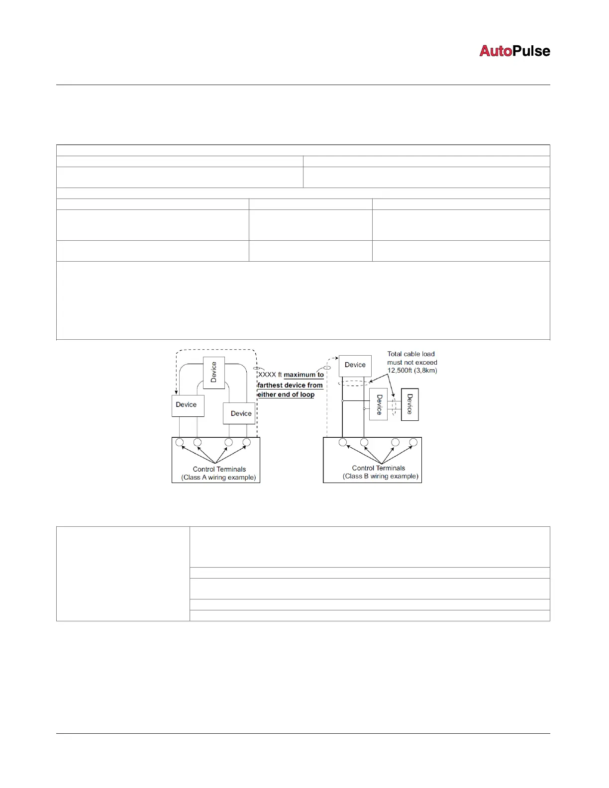
• The maximum wiring distance is the maximum distance from both the IDNet control terminals (primary and return) to the farthest
device on the circuit. See Figure 18.
• The maximum wiring distance is determined by either reaching the maximum resistance, the maximum capacitance, or the stated
maximum distance, whichever occurs first.
• The total circuit cable load (amount of cable used) must not exceed 12,500 ft (3,8 km).
• Twisted wiring is recommended for improved noise immunity.
Figure 18: Maximum wiring distance
Table 15: IDNet wiring considerations
External wiring must be shielded (for lightning suppression) and 2081-9044 Overvoltage Protectors
must be installed at building exit and entrance locations.
For more information, refer to the Model 2081-9044 Overvoltage Protector Installation Instructions
(579-832).
Capacitance; each protector adds 0.006 µF across the connected line.
Resistance; each protector adds 3 ohms per line of series resistance; both IDNet wires are
protected; 6 ohms per protector will be added to the total loop resistance.
The maximum distance of a single protected wiring run is 3270 ft (1 km).
IDNet wiring considerations
using 2081-9044 Overvoltage
Protectors
(2081-9044 is UL listed to Standard
1459, Standard for Telephone
Equipment)
See the 2081-9044 Overvoltage Protector Installation Instructions (574-832) for additional information.
page 24 579-1102AR Rev C
Z-20 Agent Releasing Panel Installation Manual
 Loading...