51
use and maintenance
SR 50
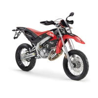
REMOVING THE LOWER
HANDLEBAR COVER
Carefully read p. 39 (MAINTENANCE).
◆ Remove the cover support element, see
p. 50 (REMOVING THE COVER SUP-
PORT ELEMENT).
NOTE Support the front part of the fairing
(1), to prevent it from accidentally falling
down.
◆
Unscrew and remove the two screws (2).
Handle the plastic or painted components
with care and avoid scraping or damag-
ing them.
◆ Remove the front part of the fairing (1).
◆ Take the spacer (3).
◆
Unscrew and remove the screw (4).
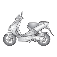
◆
Rotate the handlebar completely right-
wards, unscrew and remove the screw (5)
(with shorter diameter) and the screws (6)
(7) and (8).
NOTE Upon reassembly, fit the screws (5)
(with shorter diameter) in the relevant seats.
◆ Rotate the handlebar in central position,
withdraw the lower handlebar cover (9)
from the front and remove it.
PARTIAL REMOVAL OF THE
UPPER HANDLEBAR COVER
Carefully read p. 39 (MAINTENANCE).
◆ Remove the rear-view mirrors, see p. 53
(REMOVING THE REAR-VIEW MIR-
RORS).
◆ Remove the lower handlebar cover, see
beside (REMOVING THE LOWER HAN-
DLEBAR COVER).
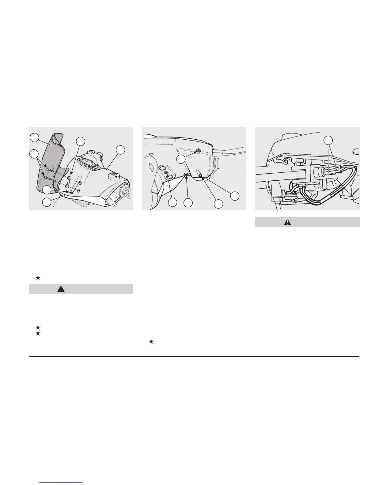
◆
Disconnect the two electric terminals
(10).
The upper handlebar cover (11) (complete
with switches, instruments and indica-
tors) remains connected with the speed-
ometer cable and with the electric cables,
which makes it impossible to remove it
completely.
Proceed with care in order to avoid dam-
aging the components.
◆ Paying attention to the two switch connec-
tions (12), lift the upper handlebar cover
and rotate it forwards, then rest it on the
front shield.
NOTE Upon reassembly, when position-
ing the upper handlebar cover, pass the elec-
tric terminal cables (10) behind and under
the handlebar.
4
3
1
2
9
11
12
2
5
7
8
10
CAUTION
CAUTION
 Loading...