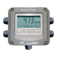
ATI Q46D Dissolved Oxygen System Part 10 - Troubleshooting
54
O&M Manual
Rev-N (4/21)
7. On relay based systems, check the load that is connected to the relay
contacts. Verify the load is within the contact rating of the relays. Relay
contacts which have been used for higher power AC current loads may
become unsuitable for very low signal DC loads later on because a small
amount of pitting can form on the contacts. If the load is highly inductive
(solenoids, motor starters, large aux relays), note that the contact rating will
be de-rated to a lower level. Also, due to the large amount of energy present
in circuits driving these types of loads when they are switched on an off, the
relay wiring placement can result in electrical interference for other devices.
This can be quickly resolved by moving wiring, or by adding very inexpensive
snubbers (such As Quencharcs) to the load.
8. Carefully examine any junction box connections for loose wiring or bad wire
stripping. If possible, connect the sensor directly to the analyzer for testing.
9. Check sensor membrane for fouling. Look closely for signs of grease or oil
which may be present. Replace membrane and electrolyte, allow to stabilize,
and re-check. The procedure in Oxygen Sensor Assembly, on page 26,
must be followed when replacing the membrane.
10.3 Analyzer Tests
1. Disconnect power and completely disconnect all output wiring coming from
the analyzer. Remove sensor wiring, relay wiring, and analog output wiring.
Re-apply power to the analyzer. Verify proper voltage (115 or 230 VAC) is
present on the incoming power strip of the analyzer, and that the analyzer
power label matches the proper voltage value.
2. If analyzer does not appear to power up (no display), remove power and
check removable fuse for continuity with a DVM.
3. If analyzer does power up with a display, use the “Simulate” feature to check
operation of the analog outputs (and relays contacts with a DVM.)
4. Check sensor power circuits. With a DVM, verify between -4.5 and -5.5 VDC
from sensor connection terminals WHITE (+) to BLACK (-). Then verify
between +4.5 and +5.5VDC from GREEN (+) to BLACK (-).
5. Check TC drive circuit. Place a wire-short between the RED and BLACK
sensor terminals. With a DVM, measure the voltage between the BLACK (-)
and BROWN (+) sensor terminals to verify that the TC drive circuit is
producing about -4.6 to -5.5 VDC open-circuit. Remove DVM completely and
connect a 1000 Ohm resistor across the BLACK to BROWN terminals. The
temperature reading on the front LCD should display approximately 0°C and
the dissolved oxygen reading should display approximately 0 ppm.

 Loading...