Viewing A Run
Each time a fastening process occurs, the RE Qualifier captures
the analog information associated with the pneumatic signal. The
RE Qualifier can hold up to
ten seconds worth of analog
information.
This analog signature can be
viewed with the current
parameter set overlaid on top
of it. In order to view the
run, press the VIEW RUN
soft-key while the unit is
showing the main screen.
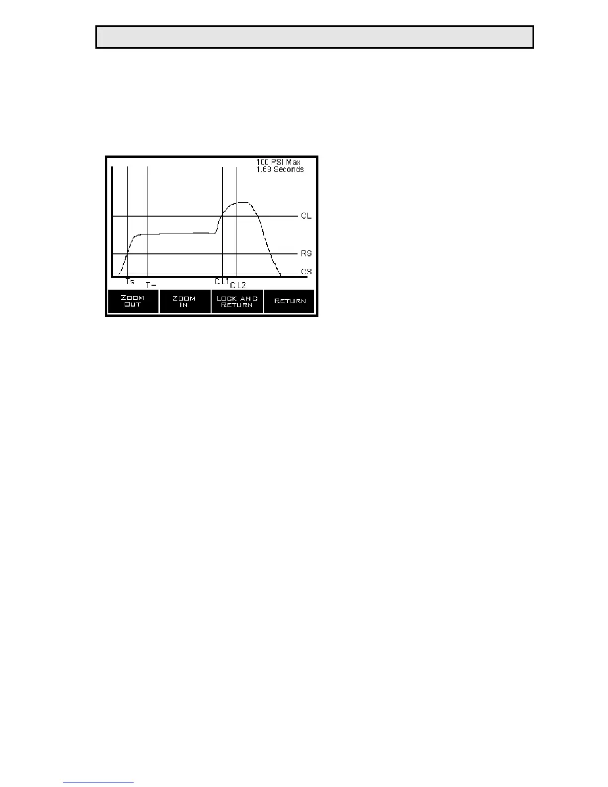
The screen will say “Loading” while the information to generate
the graph is collected. Once the data for the graph is gathered, a
screen similar to the one above will appear.
The horizontal axis on this screen represents time. The vertical
axis represents pressure. In the upper right hand corner of the
screen is a legend that tells the user what the time and pressure
scale are for this particular graph.
Horizontal lines will appear on top of the graph. These lines will
represent the Cycle Start (CS), Run Start (RS) and Clutch Level
(CL). The cycle start level is a parameter setting that tells the unit
when to start and stop collecting data. If the pressure is above the
cycle start level, data is gathered for viewing and auto-calibration
purposes.
Once the pressure rises above the run start level, some kind of sta-
tus will be generated at the end of the run (ie. Cycle OK, Batch
OK, or a reject of some type).
RE Qualifier System Manual 8
 Loading...