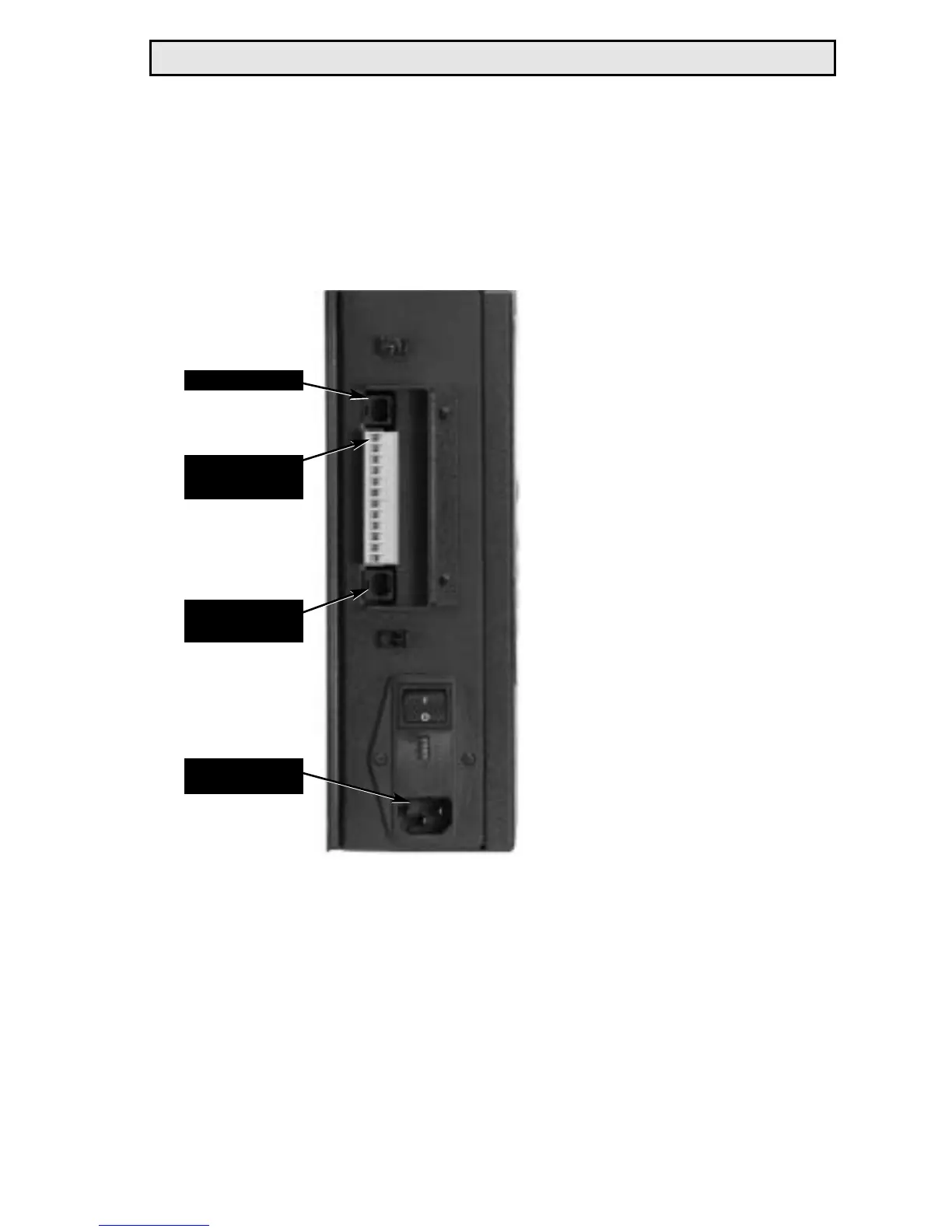
I/O Structure
RS-232 Connector
The RS-232 Connector is used to communicate with external seri-
al devices (like a computer). The connector is a standard RJ-11
connector. Pin 1 on the
connector is the top-most
pin as pictured in the fig-
ure to the left. The pin-
out is as follows:
1 N/C
2 N/C
3RX
4TX
5 GND
6 N/C
I/O Connector
The I/O Connector is
used to provide discreet
signals to external
devices (like a PLC). Pin
1 is located at the top of
the connector as pictured
in the figure to the left.
The pin-out is as follows:
1 RS485- 7 GND/OPTO COM
2 RS485+ 8 RESET INPUT
3 REJECT RELAY 9 SUSPEND INPUT
4 BATCH RELAY 10 PARAM B INPUT
5 CYCLE RELAY 11 PARAM C INPUT
6 +24VDC/RLY COM 12 PARAM D INPUT
RE Qualifier System Manual 24
RS-232 Connector
Remote Transducer
Connector
I/O Connector
(pin 1)
Power Entry
Module
 Loading...