2-3. Installation on the Pipe
2-3-1. Standard Installation Example
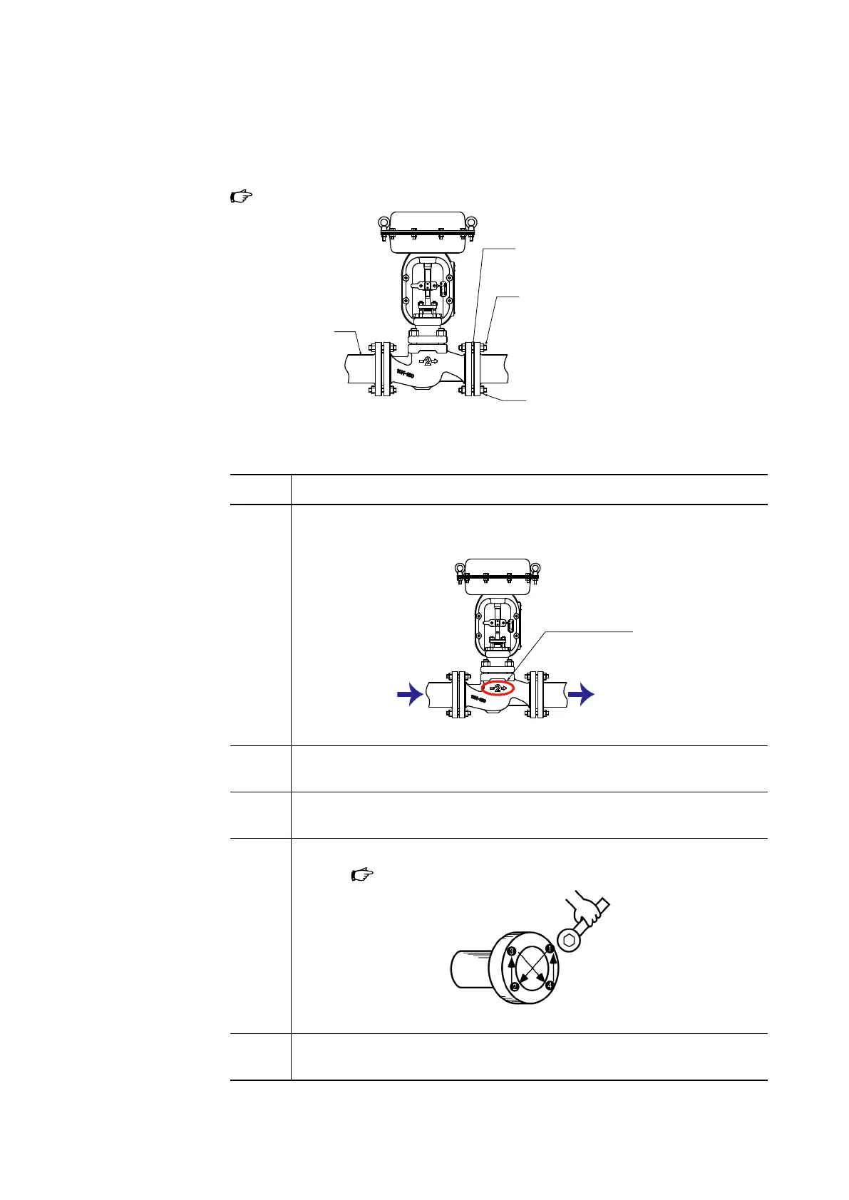
Figure 2-2 illustrates standard installation.
Gasket
Bolt
Figure 2-2. Installation on the pipe
2-3-2. Installation method
Step Procedure
1 Check that the flow direction of the process fluid is the same as the direction
indicated on the control valve.
Flow direction
indicated on the valve
Figure 2-3. Flow direction indicated on the valve
2 Attach the valve and gaskets to the pipes. Loosely tighten the nuts of the
flange bolts.
3 Make sure that the gaskets do not protrude into the flow path and constrict
the inner diameter of the valve.
4 Tighten the bolts and nuts for the flanges evenly and securely in a diagonal
pattern (
Figure 2-4).
Figure 2-4. Tightening in a diagonal pattern
5 After installation is complete, check that all bolts and nuts are securely tight-
ened and there is no leak from the piping.
2-5

 Loading...
