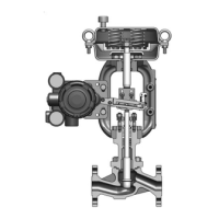
6-5. Disassembly of the Side Handwheel
Disassembly procedure
Check the size of the actuator and disassemble the side handwheel, referring to
Figure 6-15.
Step Procedure
1 Check that the pointer on the side handwheel main unit is in the AUTO position. Remove
the side handwheel from the actuator.
2 Loosen the bolts and nuts that hold the levers. Remove the bosses of the lever drive nut
from the holes near the bottom edge of the levers.
3 Loosen and remove the lock nut from the handwheel, and remove the handwheel from
the side handwheel main unit.
4 Loosen and remove the pan-head screw with captive spring washer that hold the shaft
holder. Remove the shaft holder and the shaft. Remove the bearing and the lever drive
nut from the shaft holder.
5 Remove the bolts and nuts that hold the levers, and remove the levers from the side
handwheel main unit to complete the disassembly.
6-6. Assembly of the Side Handwheel
Assembly procedure
Check the size of the actuator and assemble the side handwheel, referring to
Figure 6-15.
Step Procedure
1 Insert the levers into the side handwheel main unit, and hold them temporarily with the
bolts and nuts for the levers.
2 Attach the operation nut and the pair rings to the shaft. Insert the threaded part of the
shaft through the hole for the shaft in the side handwheel main unit.
3 Put the other end of the shaft into the shaft holder.
4 Hook the bosses of the lever drive nut into the holes near the bottom of the levers and
tighten the bolts and nuts holding the levers.
5 Connect the side handwheel main unit to the shaft holder using the pan-head screw
with captive spring washer, allowing the pointer attached to the lever drive nut to stick
out of the main unit.
6 Pass the shaft through the handwheel and fasten the wheel with the lock nut to com-
plete assembly of the side handwheel.
6-15

 Loading...