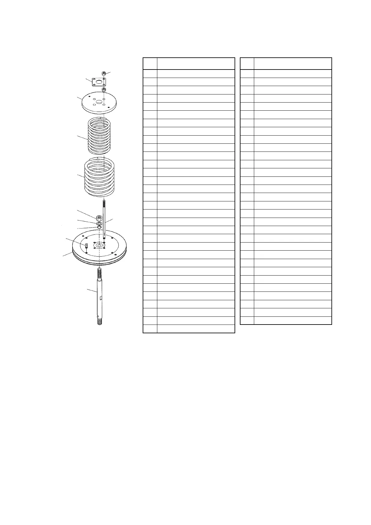
Table 7-1.
(52)
(53)
(59)
(55)
(54)
(61)
(62)
(60)
(63)
(56)
(58)
No. Part name No. Part name
1 Eyenut 33 Worm wheel
2 Hex nut 34 Slide screw
3 Spring washer 35 Lock pin
4 Long hex staybolt 36 Handwheel
5 O-ring 37 Operation instruction label
6 Piston unit 38 Spring washer
7 Tape liner 39 Locknut
8 O-ring 40 Single-column angular bearing
9 Short hex staybolt 41 Worm shaft
10 Sealing washer 42 Key
11 Spring washer 43 Gear case cap
12 Hex bolt 44 Dust seal
13 Round bushing 45 Hex bolt
14 Dust seal 46 Spring washer
15 Wear ring 47 Truss head screw
16 Nameplate 48 Indicator
17 Spring holder 49 Slide screw rotation lock
18 Rain cap 50 Hex bolt
19 O-ring 51 Hex nut
20 Lift stopper 52 Hex nut
21 Cylinder 53 Stopper holder
22 Rod packing 54 Spring (large)
23 Guide bushing 55 Spring (small)
24 Dust seal 56 Spring stopper
25 Scale 57 Piston
26 Truss head screw 58 Rod
27 Pointer 59 Spring flange
28 Stem connector 60 Stopper
29 Yoke 61 Locknut
30 Gear case 62 Spring washer
31 Bearing holder 63 O-ring
32 Single-column angular bearing
Figure 7-6. Structure of the spring unit
7-8

 Loading...
