EasyManua.ls Logo

Barco LCD 5521 V4 User Manual

Barco LCD 5521 V4
91 pages
To Next Page IconTo Next Page
To Previous Page IconTo Previous Page
Page #11 background imageLoading...
Page #11 background image
1. Preliminary Remarks
1.2.1.1 Connecting the device with the AC inlet
When connecting the device with the AC inlet, make sure that the power cords you use follow the specifications
mentioned below:
Mains lead (AC Power cord) with CEE 7 plug:
The wires of the mains lead are colored in accordance with the following code:
yellow + green
Earth (Ground)
blue
Neutral
brown
Line (Live)
Power cord with NEMA 5-15 plug:
The wires of the power cord are colored in accordance with the following code.
Green or Green/Yellow:
Earth (Ground)
White or Blue:
Neutral
Black or Brown:
Line ( Live)
The cord set must be UL-approved and CSA-certified.
The minimum specification for the flexible cord is No. 18 AWG Type SVT or SJT, 3-conductor.
The cord set must have a rated current capacity of at least 10A.
The attachment plug must be an Earth-grounding type with a NEMA 5-15P (10 A, 125 V) configuration.
Power cord with GB 2099 plug:
The wires of the power cord are colored in accordance with the following code.
yellow + green
Earth (Ground)
blue
Neutral
brown
Line ( Live)
Barco - LCD 5521 V4 - R591734 - Installation manual - Revision 00 - March-2017
__________________________________________________________________________
11
Question and Answer IconNeed help?

Do you have a question about the Barco LCD 5521 V4 and is the answer not in the manual?

Barco LCD 5521 V4 Specifications

General IconGeneral
Screen Size55 inches
Brightness700 cd/m²
Contrast Ratio4000:1
Response Time8 ms
Aspect Ratio16:9
Resolution1920 x 1080
Viewing Angle178° (H) / 178° (V)
Input ConnectorsDVI, VGA, HDMI, DisplayPort

Summary

Preliminary Remarks

Styles and Symbols

Explains typographic styles and symbols used for clarity and safety in the manual.

Safety Information and Precautions

Details safety precautions for installation, operation, and maintenance, including general rules and specific warnings.

Mechanical Setup

Tools for Installation

Lists all necessary tools required for the mechanical setup of the system.

Scope of Delivery

System Components Overview

Describes the main components: front access mount, display, pedestal, and wall mount solutions.

Display Mechanics Adjustment

Pedestal Width Adjustment

Explains how to adjust pedestal width using spacers for different display types.

Front Access Mount Width Adjustment

Details width adjustment for the front access mount module via spacers.

Pedestal Wall Setup

Overview and Preparation

Overviews pedestal system components and details initial preparation and wall fixation.

Connection Concept and Installation

Explains the T-bar connection concept and provides detailed steps for pedestal installation and module mounting.

Floor Fixation and Finalization

Covers securing the display wall to the floor and performing final structural adjustments.

Wall Mount Setup

Wall Mount System Components

Introduces the wall mount solution, aluminum profiles, and panel mechanics.

Profile Alignment and Installation

Details profile positioning, alignment, spacing calculations, spacer use, and drilling for wall mounts.

Frame Mounting, Grounding, and Checks

Covers frame fixing, grounding, bracket installation, and final alignment checks for wall mount solutions.

Cabling

Power and Data Cabling

Explains power, data, and LAN cabling principles, including cable routing and management.

Grounding Procedure

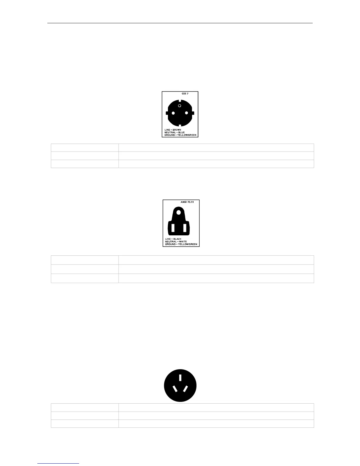
Details the steps for grounding the display system to the power network.

Display Installation

Mounting and Connection Steps

Provides a comprehensive step-by-step guide for mounting and connecting displays, including interface adjustments.

Safety for System Access

Outlines critical safety precautions for maintenance on monitors integrated within a structure.

Wall Distance

Distance Calculations

Lists specific distances to the wall based on configuration angle and module number.

Addresses

Contact and Support

Provides Barco's contact details for sales, support, and general inquiries.

Related product manuals