9. Distance to the wall
9 Distance to the wall
The video wall has to be fixed to the wall. In case of a linear setup, and in case the wall is in parallel to the video
wall, every system has the same distance to the wall.
In case of curved setup, the distance to the wall increases with every system.
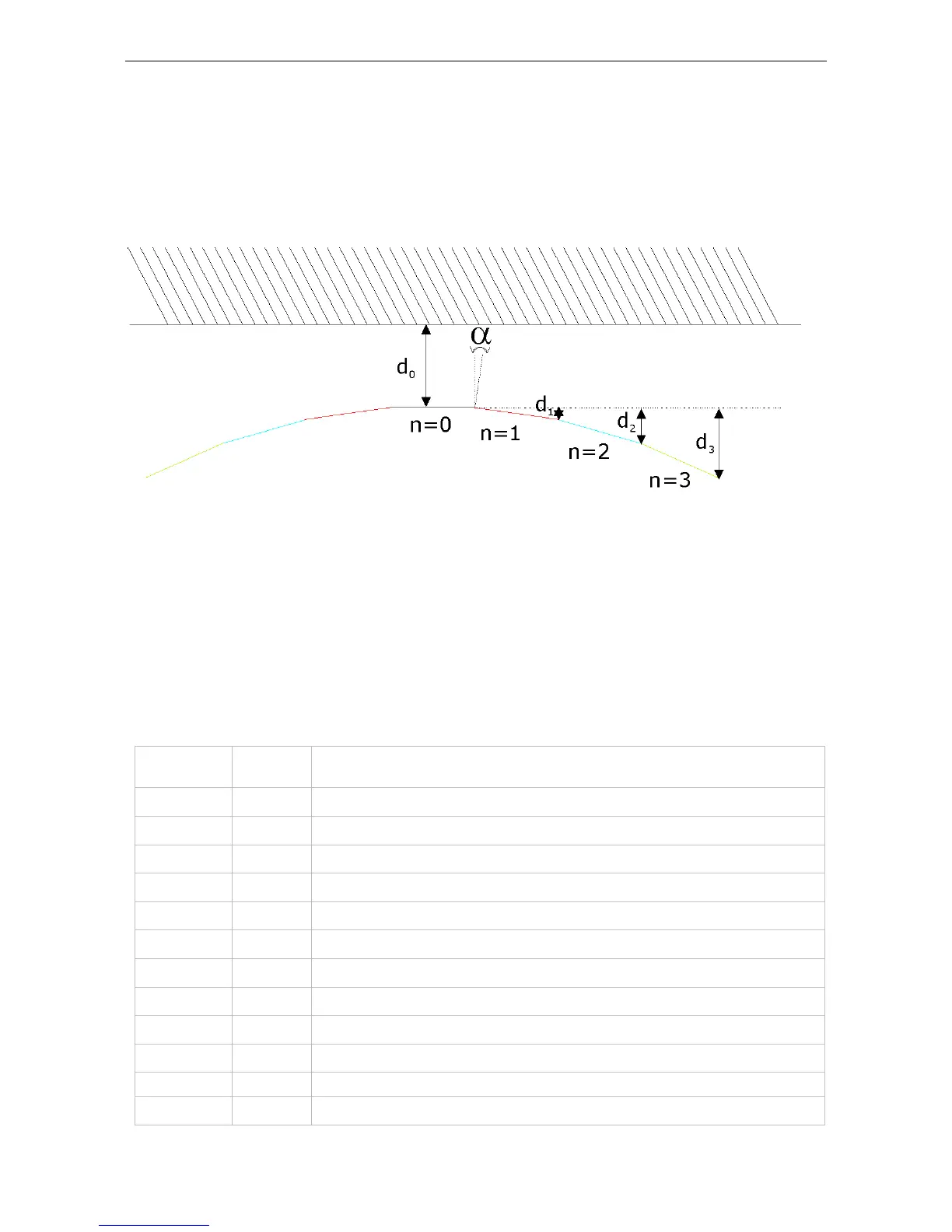
The following drawing introduces the nomenclature:
d
o
is the distance of the center module from the wall. α is the configuration angle, e.g. 3°, 5°, 8°.
n
1
is the first module next to the center module
n
2
is the seconded module next to the center module; and so on
d
1
is the distance of the outer edge of n1 to the reference plane of n
0
.
d
2
is the distance of the outer edge of n2 to the reference plane of n
0
; and so on.
The following table lists the distances of the outer edges to the reference plane of n
0
depending on the configu-
ration angle.
Configuration
angle
Module # Distance to reference plane
3° 1
d
1
=63.6mm
3° 2
d
2
=190.64mm
3° 3
d
3
=380.75mm
3° 4
d
4
=633.43mm
3° 5
d
5
=947.97mm
3° 6
d
6
=1323.52mm
3° 7
d
7
=1759.04mm
3° 8
d
8
=2253.35mm
3° 9
d
9
=2805.08mm
3° 10
d
10
=3412.73mm
5° 1
d
1
=105.92mm
Barco - LCD 5521 V4 - R591734 - Installation manual - Revision 00 - March-2017
_____________________________________________________________
88
 Loading...