1 689 975 223 2013-10-21| Robert Bosch GmbH
16 | ACS 751/651 | Scalesen
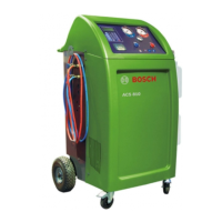
4.3 Entering the debug mode
1. Connect the power cable to the mains supply.
2. Switch on the power supply.
3. Press the C key and power on the ACS 751/651.
4. Enter the password 33284.
"The "Debug Mode" menu is displayed.
4.4 Overview of actuators
i See chapter 15 for the hydraulic circuit diagram.
Actuator name Description
CTRL Entry to internal tank
CX Compressor
CXOL Compressor oil return
FA Fan
HL Connection from LP to HP
HPS High pressure switch
IN Entry to liquefier
LP Entry through LP hose
OD Oil drain
OI Oil recharge
PRIN Passage for clearing
PTA/PSA Pressure sensor for accumulator
PTT/PST Pressure sensor for tank
PTV/PSV Pressure sensor for vacuuming
PU Air purge on refrigerant cylinder
RE Connection between internal refrig-
erant cylinder and manifold
UV UV dye recharge
VC Vacuum pump
VISO Connection between vacu-
um pump and manifold
5. Scales
5.1 Calibration of scales
5.1.1 Fresh Oil / used oil / UV dye scales
1. Open the service hatch on the front panel.
2. In the main menu, select "ACS Settings" and press E.
? The ACS Settings menu is displayed.
3. Select "Calibration".
4. Select "Balance Calibration".
5. Enter the password 227.
? The following screen is displayed.
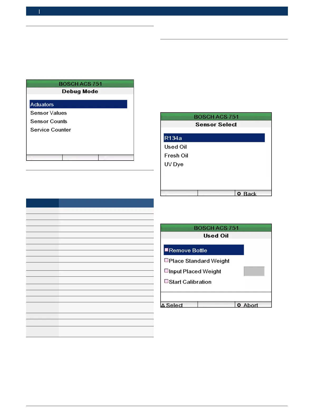
6. Select any of the sensors - fresh oil, used oil or UV dye.
? The following screen is displayed.
7. Detach the bottle from the connector.
8. Select "Remove Bottle".
9. Attach the calibrating weight to connector of the oil
/ UV dye sensors.
 Loading...