1 689 975 223 2013-10-21| Robert Bosch GmbH
38 | ACS 751/651 | Hydraulic circuit diagramen
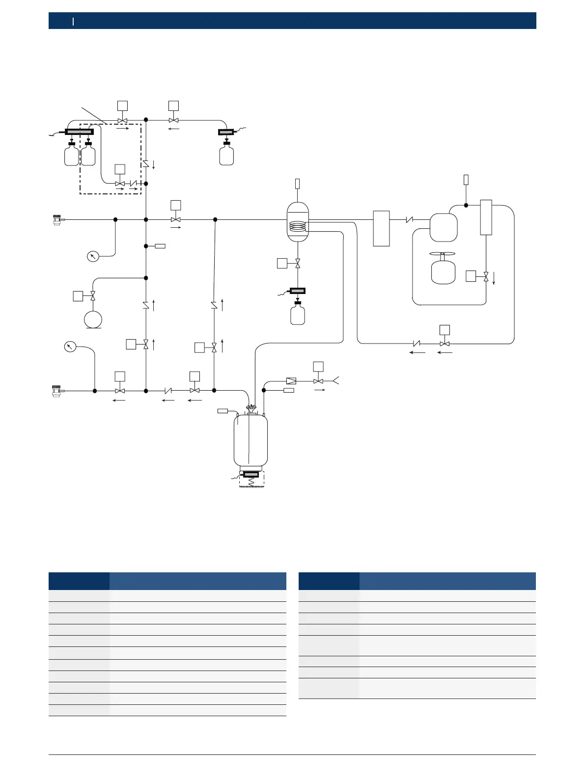
17. Hydraulic circuit diagram
Y10 Y11
LC3
LC4
Y13
POE
CV8
CV7
OI UV
B4
POE
OIL
PAG
OIL
UV DYE
CHARGE
HP
COUPLING
HIGH
Y4
VISO
M1
VACUUM PUMP
LOW
Y5
CV6
HL
Y6
LP
IN
B5
PT3
CV5
RE
Y2
Y7
PRIN
CV4
B6
PT1
HEATED
SUCTION
ACCUMULATOR
Y12
OD
LC2
B2
OIL DRAIN
ORIFICE
Y8
PUR
PT2
B7
L V
TEMP
SENSOR
B8
B1
LC1
INTERNAL
CYLINDER
COMBO
FILTER
CV2
COMPRESSOR
M2
M3
FAN
B9
SS
OIL
SEPARATOR
Y9
CXOL
CV3
CTRL
459877_73Nkv
only for
POE option
LP
COUPLING
To atmosphere
Fig. 35: Hydraulic circuit diagram
i "LC" denotes a "scale". For example, "LC-OI" represents the scale for fresh oil.
Actuator name Description
CTRL Entry to internal tank
CX Compressor
CXOL Compressor oil return
FA Fan
HL Connection from LP to HP
HPS High pressure switch
IN Entry to liquefier
LP Entry through LP hose
OD Oil drain
OI Oil recharge
PRIN Passage for clearing
Actuator name Description
PTA/PSA Pressure sensor for accumulator
PTT/PST Pressure sensor for internal refrigerant bottle
PTV/PSV Pressure sensor for vacuuming
PU Air purge on internal refrigenrant bottle
RE Connection between internal re-
frigerant bottle and manifold
UV UV-dye recharge
VC Vacuumpump
VISO Connection between vacu-
um pump and manifold
 Loading...