1 689 975 223 2013-10-21| Robert Bosch GmbH
Test Points | ACS 751/651 | 37ACS 751/651 | 37 | 37 en
16. Test Points
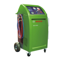
HMI board
Test point name Expected voltage (V) Remarks
Minimum Typical Maximum
TP1 11.4 12 12.6 If the voltage is out of range, check the SMPS.
TP2 3.234 3.3 3.37 If the voltage is out of range, there may be a
problem with in-built regulators of HMI board
TP3 4.75 5 5.25 If the voltage is out of range, check the SMPS.
TP4 1.176 1.2 1.22 If the voltage is out of range, there may be a
problem with in-built regulators of HMI board.
TP5 --- 16.5 ---
±10% variation is allowed. Check these volt-
ages only if the LCD has any problem.
TP6 --- -8.1 ---
TP7 --- 8.5 ---
TP8 --- 2.4 ---
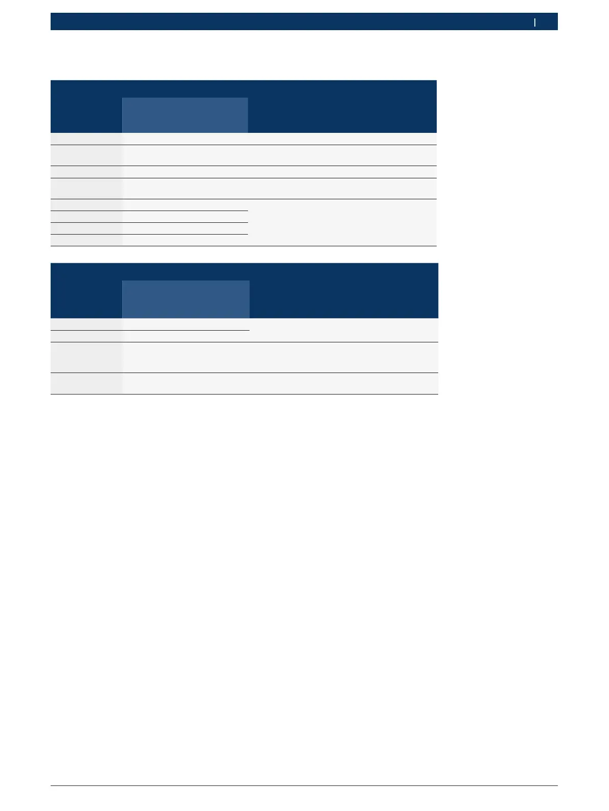
I/O board
Test point name Expected voltage (V) Remarks
Minimum Typical Maximum
TP1 4.75 5 5.25 If the voltage is out of range, check the SMPS.
TP2 11.4 12 12.6
TP3 5.09 5.17 5.25 If the voltage is out of range, there
may be a problem with in-built reg-
ulators of the I/O board.
TP10 3.219 3.3 3.371 If the voltage is out of range, there may be a
problem with in-built regulators of the I/O board
 Loading...