1 689 975 223 2013-10-21| Robert Bosch GmbH
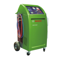
24 | ACS 751/651 | Boardsen
8. Boards
8.1 Replacing the HMI board
Danger - Electric shock hazard!
Touching live parts of the power switch or
on the power board can result in serious
injury or death.
¶ Disconnect the mains connection.
¶ Wear ESD protective gear.
1. Open the HMI (chap. 7.1)
2. Undo all the connections to the HMI board.
3. Unfasten the HMI board from the HMI module.
4. Place the new HMI board in position.
5. Fasten the HMI board to the HMI module.
6. Complete all the electrical connections to the HMI
board.
7. Close and fix the HMI module back in position.
8.2 Replacing the Switch Mode Power
Supply (SMPS)
Danger - Electric shock hazard!
Touching live parts of the power switch or
on the power board can result in serious
injury or death.
¶ Disconnect the mains connection.
¶ Wear protective ESD gloves.
1. Switch off the ACS 751/651.
2. Open the top panel.
3. Disconnect the mains connection.
4. Disconnect the electrical connections to the SMPS.
5. Unfasten the SMPS from the board.
6. Place the new SMPS in place and fasten the screws.
7. Restore the connections to the SMPS.
8. Close the top panel.
8.3 Replacing the I/O board
Danger - Electric shock hazard!
Touching live parts of the power switch or
on the power board can result in serious
injury or death.
¶ Disconnect the mains connection.
¶ Wear ESD protective gloves.
1. Switch off the ACS 751/651.
2. Open the rear panel.
3. Disconnect the mains connection and the electrical
connections to the I/O board.
4. Unfasten and remove the main board.
5. Place the new board in position.
6. Fasten the screws on the board.
! Hold the board tightly while fastening the screws on
the board. If the board is dropped down, it might be
damaged.
7. Restore the electrical connections to the I/O board.
8. Close the rear panel and fasten the screws of the
rear panel.
 Loading...