1 689 975 223 2013-10-21| Robert Bosch GmbH
Replacing the wiring harness | ACS 751/651 | 33ACS 751/651 | 33 | 33 en
13. Replacing the wiring
harness
i See chapter 16 for the electrical terminal diagram
Danger - Electric shock hazard!
Touching live parts of the power switch or
on the power board can result in serious
injury or death.
¶ Disconnect the mains connection.
¶ Use ESD protection.
13.1 Replacing the wiring harness 1
1. Switch off the ACS 751/651.
2. Disconnect the mains connection.
3. Remove the top, rear and left panels
(chap. 6.1, 6.3, 6.5).
4. Disconnect the cable from connector X19 and X20
on the I/O board.
5. Cut the cable ties and remove the harness.
6. Disconnect the AC connector P1 on the SMPS.
7. Remove the earthing terminal on I/O plate near the
SMPS.
8. Unfasten the connector on the vacuum pump.
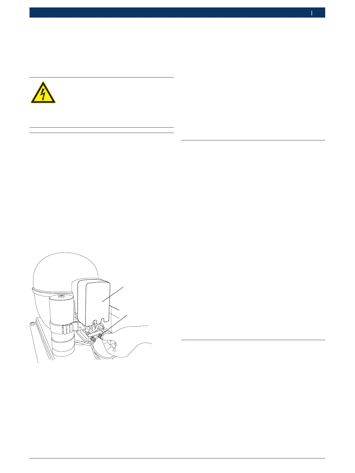
9. Pull up the compressor electrical cover by loosening
the side screw (4 to 5 threads).
10. Pull the cord relief by loosening the 2 screws.
459897_43Nkv
1
2
Fig. 34: Compressor connections
1 Cover
2 Cord relief
11. Undo the fan connections.
12. Disconnect the cable B9 to the pressure switch on
the manifold.
13. Undo the respective earthing connections.
14. Place the new wiring harness in position.
15. Make the respective earthing connections.
16. Connect the cable B9 to the pressure switch on the
manifold.
17. Place the cord relief by loosening the 2 screws.
18. Fix the compressor electrical cover by tightening
the screw (4 to 5 threads).
19. Fix the connector on the compressor by tightening
the side screw.
20. Connect the cable to connector X19 and X20 on the
I/O board.
21. Fix the earthing terminal on I/O plate near the
SMPS.
22. Connect the AC connector P1 on the SMPS.
23. Fix the cable ties.
24. Fix the top, rear and left panels.
13.2 Replacing the wiring harness 2
i See chapter 16 for the electrical terminal diagram.
1. Switch off the ACS 751/651.
2. Disconnect the mains connection.
3. Remove the front, and rear panels (chap. 6.1, 6.3).
4. Remove the earthing terminal from:
$ Vacuum pump plate
$ Compressor plate
$ Fan body
$ Base plate
$ Scales
5. Cut the cable ties and remove the harness.
6. Remove the five earthing terminals on the earthing
plate.
7. Place the new wiring harness in position.
8. Fix the five earthing terminals on the earthing plate.
9. Fix the earthing terminal on:
$ Vacuum pump plate
$ Compressor plate
$ Fan body
$ Base plate
$ Scales
10. Fix the cable ties.
11. Fix the front and rear panels.
13.3 Replacing the wiring harness 3
i Power supply SMPS to I/O board.
1. Switch off the ACS 751/651.
2. Disconnect the mains connection.
3. Remove the top and rear panel (Chap. 6.1, 6.3).
4. Remove the cable from the connector P2 on the
SMPS.
5. Remove the cable from X1 connector on I/O board.
6. Place the new wiring harness in position.
7. Fix the cable to P2 connector on SMPS.
8. Fix the cable to X1 connector on I/O board.
9. Fix the top and rear panel.
 Loading...