1 689 975 223 2013-10-21| Robert Bosch GmbH
26 | ACS 751/651 | Refrigerant cylinderen
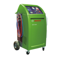
9.3 Replacing the air purge manifold on
the cylinder
1. Perform hose drain.
2. Switch off the ACS 751/651.
3. Open the right panel and the rear panel (see chap-
ter 6.3, 6.4).
4. Close the LP valve on the internal refrigerant cylinder.
2
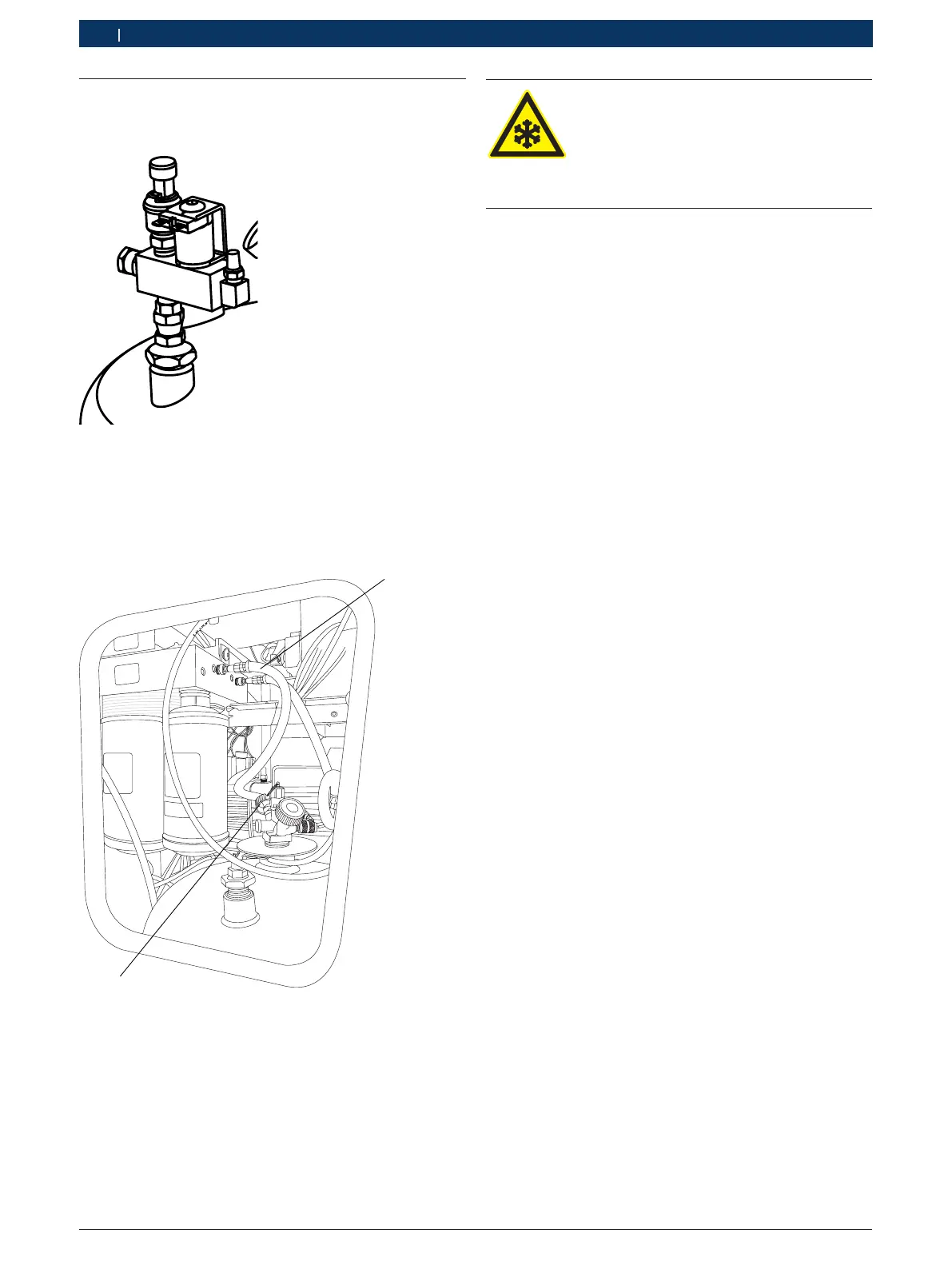
Fig. 27: Hose connections to cylinder and manifold
1 LP hose from manifold
2 LP valve
5. Remove the LP hose connection on the cylinder side.
i Some refrigerant might escape when the LP hose is
removed. It is recommended to wear safety gloves
Risk of frostbite!
A small quantity of refrigerant might
escape when the LP hose is disconnected
from the cylinder.
¶ Wear safety gloves.
6. Connect the LP hose from manifold to the external
cylinder and open the LP valve on the external cylin-
der.
7. Start the ACS 751/651 in debug mode.
8. Select CTRL, RE, HL, IN, CX and FA.
9. Monitor the PST (mbar) and R134a (g) values.
10. Deselect CTRL, RE, HL, IN, CX and FA when the
PST pressure reaches zero mbar and the value of
R134a reaches approximately 1000 g.
11. Select CXOL for 30 seconds at the end of the
process.
? The internal cylinder is now empty.
12. Disconnect the metripack and solenoid connec-
tions on the air purge manifold.
13. Hold the positioning nut on the air purge manifold
and loosen the adapter. Detach the air purge mani-
fold from the cylinder.
14. Connect the new air purge manifold using Loc-
tite 577.
15. Connect the metripack and solenoid connection to
the main supply.
16. Connect the blue hose to the Y-valve of the internal
refrigerant tank.
i Ensure that the hoses are routed in the correct
orientation and do not touch the panels or other
internal parts.
17. Bind the tank hoses with the spiral.
18. Open the LP valve on the Y-valve of the refrigerant
cylinder.
19. Close the right and rear panels.
"The temperature sensor is replaced.
 Loading...