16 en | Installing the Pipe Mount AutoDome Pipe Mount
F.01U.251.410 | 1.0 | 2011.08 Installation Guide Bosch Security Systems, Inc.
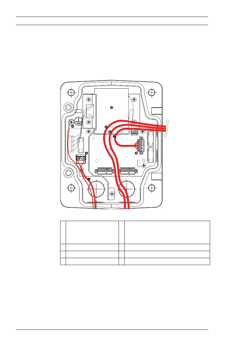
2.5.1 Methods for Routing Wires
There are two possible methods to route the video, control, and
alarm wires:
– One is to route the video, control, and alarm wires through
the conduit fitting on the right (front) side of the Power
Supply Box and out to the AutoDome Interface Board.
Figure 2.3 VG4-A-PSU1 or VG4-A-PSU2 Power Supply Box
1 120 VAC/230 VAC
Power In
5 Coax, UTP Video, or Ethernet
Wire
(Ethernet for VG5 700 Series only)
2 P101 Connector 6 Control Wire
3 Ground Connection 7 24 VAC Power Out
4 Transformer 8 P107 Connector
GND TXD
RXD
C+
C-GND TXD
RXD
C+
C-
P101
P106 P105
P107
XF102 XF103
XF101
5 4 3 2 1
1
2
J101
(LED)
HTR DOME
24V NC 24V
FUSE
FUSE
FUSE
 Loading...