EasyManua.ls Logo

Bosch VG4-A-9543 User Manual

Bosch VG4-A-9543
52 pages
To Next Page IconTo Next Page
To Previous Page IconTo Previous Page
Page #41 background imageLoading...
Page #41 background image
AutoDome Pipe Mount Cable and Wire Standards | en 41
Bosch Security Systems, Inc. Installation Guide F.01U.251.410 | 1.0 | 2011.08
3.5 Fiber Optic Module with an RS232/RS422
Controller
An AutoDome with a fiber optic module is prewired to operate
with Biphase signals only. This section describes the
procedures necessary to control a VG5 series AutoDome fitted
with a fiber optic kit using an RS232 controller or a Pelco®
RS422 controller.
To control a VG5 Series Autodome from an RS232 or from a
Pelco RS422 controller you must run control wires from the
controller to an LTC 4629 head-end fiber optic module.
This control option is applicable to the VG5 600 Series only.
3.5.1 Connecting to an LTC 4629 Head End Data/Video
Transceiver
1. Connect the RS232 cable (TxD from the controller) to the
RS232 RxD port (pin 1) of the LTC 4629.
2. Connect the ground wire of the controller to Pin 2 on the
LTC 4629.
3.5.2 Configuring the VG5 AutoDome
1. Disconnect the power to the VG4 power supply unit; then
open the unit.
2. Remove the green Serial Communications wire from the
P106 connector.
3. Remove the 100 Ω resistor across the C+ and C- pins.
4. Cut the five wires from the green Serial Communications
wire mating connector.
Ensure that the insulation covers each wire to avoid wires
from touching.
5. Cut back the insulation on the blue (ground) wire and on
the green (RxD) wire enough to be able to connect these
wires back into the P106 connector.
6. Connect the blue (ground) wire to the C- pin on the P106
connector.

Table of Contents

Question and Answer IconNeed help?

Do you have a question about the Bosch VG4-A-9543 and is the answer not in the manual?

Bosch VG4-A-9543 Specifications

General IconGeneral
BrandBosch
ModelVG4-A-9543
CategoryRacks & Stands
LanguageEnglish

Summary

Important Safety Instructions

Installing the Pipe Mount

Preparation and Options

Unpacking, parts list, tools, pre-installation checks, and mounting options.

Mount Power Supply Box

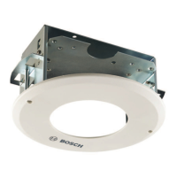
Instructions for mounting the power supply box and attaching its cover.

Wiring and Connections

Guidance on routing wires and connecting them to the power supply.

Pipe Mount and Pendant Installation

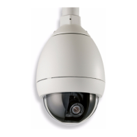
Step-by-step procedure for installing the pipe mount and attaching the pendant.

Cable and Wire Standards

Power and Distance Guidelines

Power wiring specifications and maximum cable distances for AutoDomes.

Video, Control, and Ethernet Cables

Standards for transmitting video and control via coaxial, UTP, Ethernet, and fiber optics.

Control Protocols

Information on controlling the AutoDome via Biphase, RS232, and RS485 protocols.

Fiber Optic and Audio Connections

Using fiber optic modules and audio cables for data transmission.

Alarms and Relay Connections

Alarm Input Configuration

Details on seven alarm inputs: supervised and non-supervised configurations.

Alarm Output Configuration

Configuration of dry contact relay and open collector outputs for alarms.

Related product manuals