46 en | Alarms and Relay Connections AutoDome Pipe Mount
F.01U.251.410 | 1.0 | 2011.08 Installation Guide Bosch Security Systems, Inc.
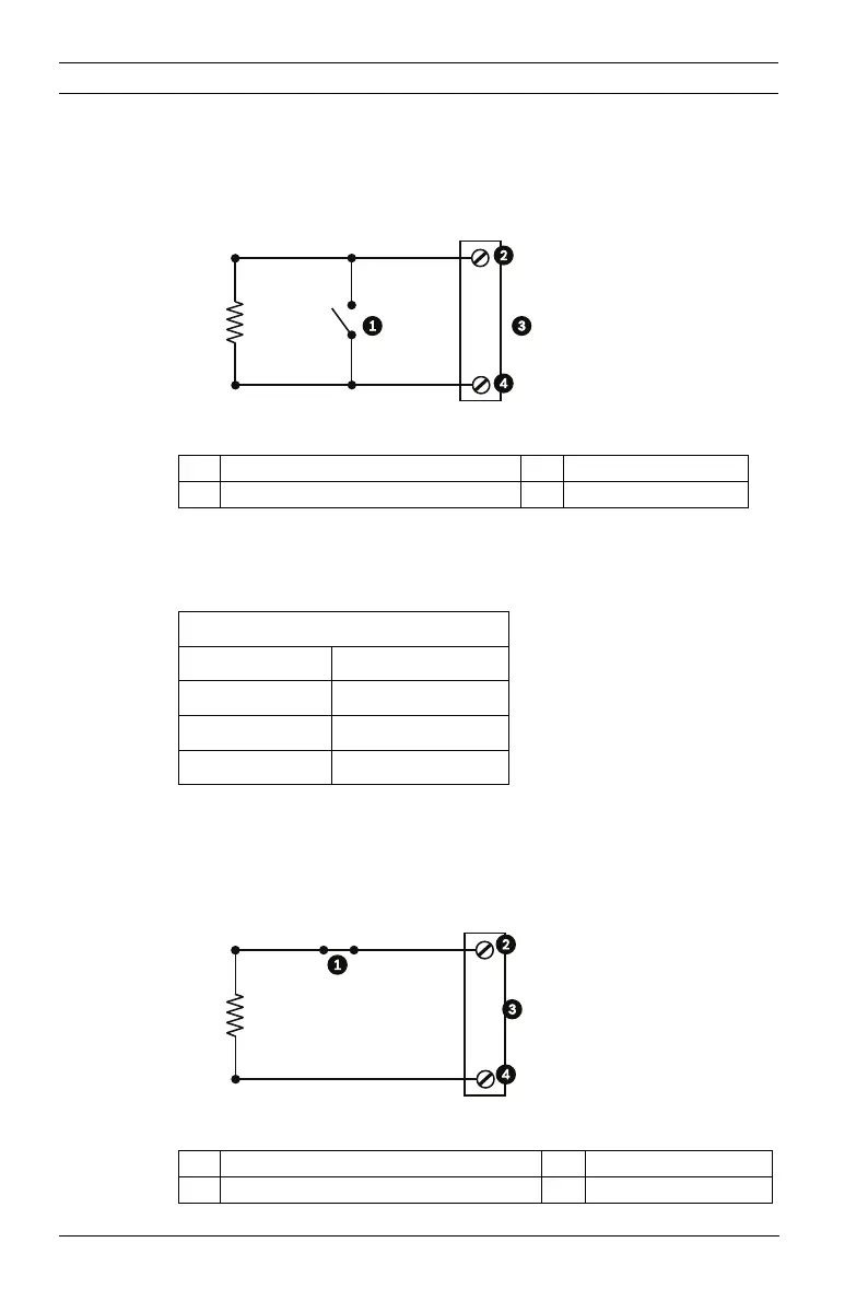
4.2.1 Configuring a Normally Open Supervised Alarm
1. Install a 2.2 K end-of-line resistor in the alarm circuit.
2. Connect the alarm wires to input 1 or 2 (pin 5 or 6) and to
the ground (pin 7) at the AutoDome.
Figure 4.1 N.O.S. - Normally Open Supervised Connections
3. From the AutoDome main menu, select Alarms
Setup>Inputs Setup, and set the Alarm Input # to N.O.S.
See the table below for contact and condition details.
4.2.2 Configuring a Normally Closed Supervised Alarm
1. Install a 2.2 K end-of-line resistor in the alarm circuit.
2. Connect the alarm wires to input 1 or 2 (pin 5 or 6) and to
the ground (pin 7) at the AutoDome.
Figure 4.2 N.C.S. - Normally Closed Supervised Connections
1 Dry Contact 3 Dome Connector
2 Alarm 1 or 2 only (Pin 5 or 6) 4 Ground (Pin 7)
AutoDome Programmed N.O.S.
Contact Alarm Condition
Open Normal
Closed Alarm
Cut or brake Tamper
2.2K
1 Dry Contact 3 Dome Connector
2 Alarm 1 or 2 only (Pin 5 or 6) 4 Ground (Pin 7)
 Loading...