.
-
04 & &#
&!
COM
COM
NC
NC
C
O
M
Rallentam.Velocità
Max.Max. Med. Min. Min.
DIS. 27370
ON
2
1345678910
N
M
PT F FC
FA
N
L
L27
L1T
E
+10
-11
1
2
3
5
7
C1
C5
GNDTXRX
9
8
710
11
1
2
12 133
6
5
4
14
18
16
15
17
p.
17 - Manual Code:
119GV18ver.
1.1 12/2011 © CAME Cancelli Automatici S.p.a. - The data and information in this manual may be changed at any time and without obligation on the part of Came Cancelli Automatici S.p.a. to notify said changes.
ENGLISH
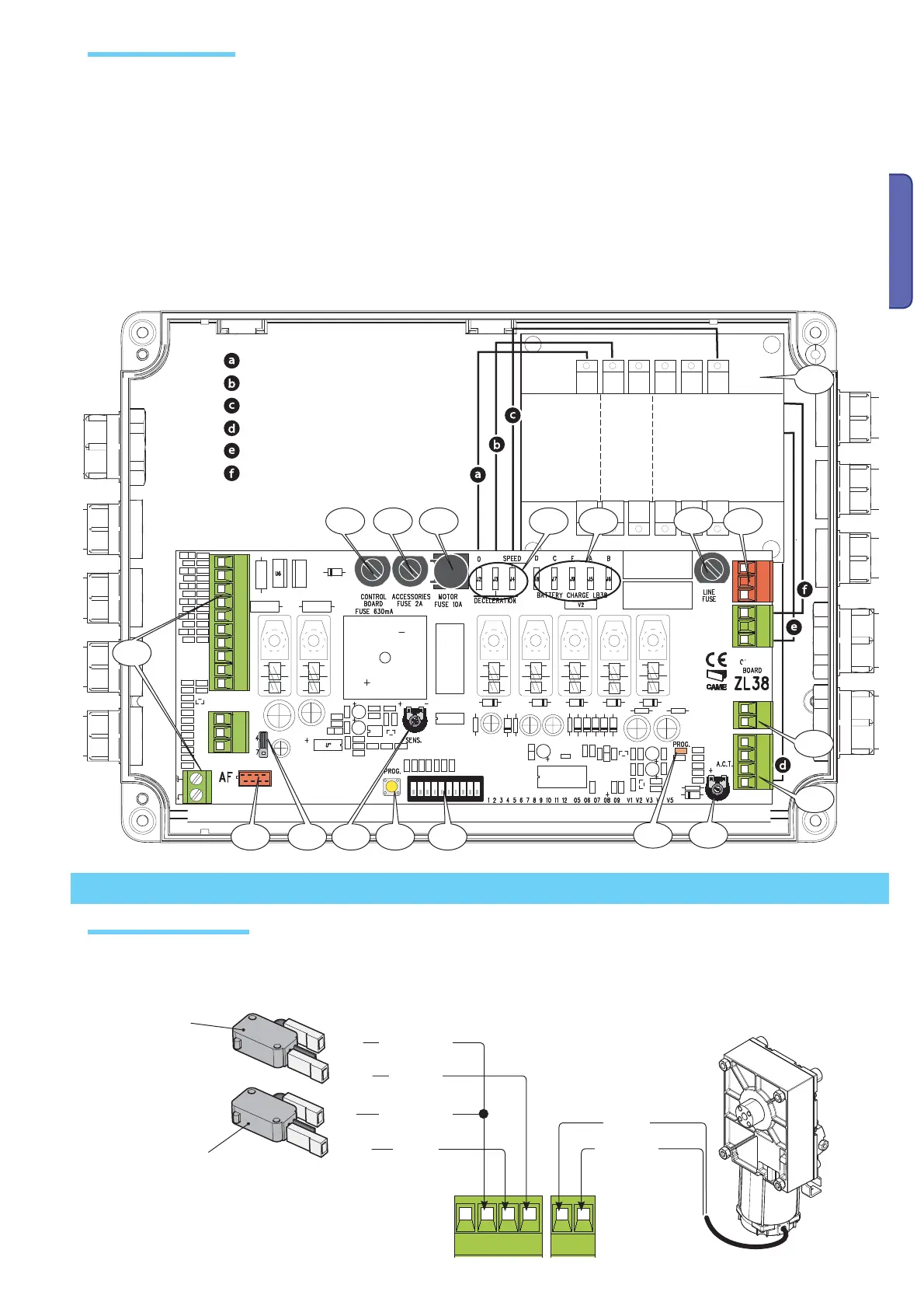
1 - Accessories fuse
2 - Line fuse
3 - control panel fuse
4 - motor fuse
5 - Accessories terminals
6 - Radiofrequency card connector
7 - SENS Trimmer:adjusting amperometric sensitivity
8 - TCA Trimmer:adjusting automatic closing time
9 - Functions selection Dip switch
10 - Code memorisation button
11 - Warning LED for radio code/automatic closing
12 - Adjustment connectors for speed and deceleration
13 - Connection connectors for 002LB38 card (battery charger)
14 - Selection jumper for command type for button on 2-7
15 - Transformer
16 - Power source terminals
17 - Motor terminals
18 - endpoint terminals
24 V DC motor
Closing micro
switch
Orange
Orange
White
Red
Blue
Brown
Opening micro
switch
Show is the connection for a left-hand barrier.A right-hand barrier has gearmotor cables inverted on terminals M-N.
White
Red
Black
Brown
Brown
Main component parts
Gearmotor and endstops
Electrical connections
Blue

 Loading...