38
BCD OUTPUT
The BCD output provides a parallel
logic-level BCD output of the
displayed weight. Additional status
signals are included. Connections
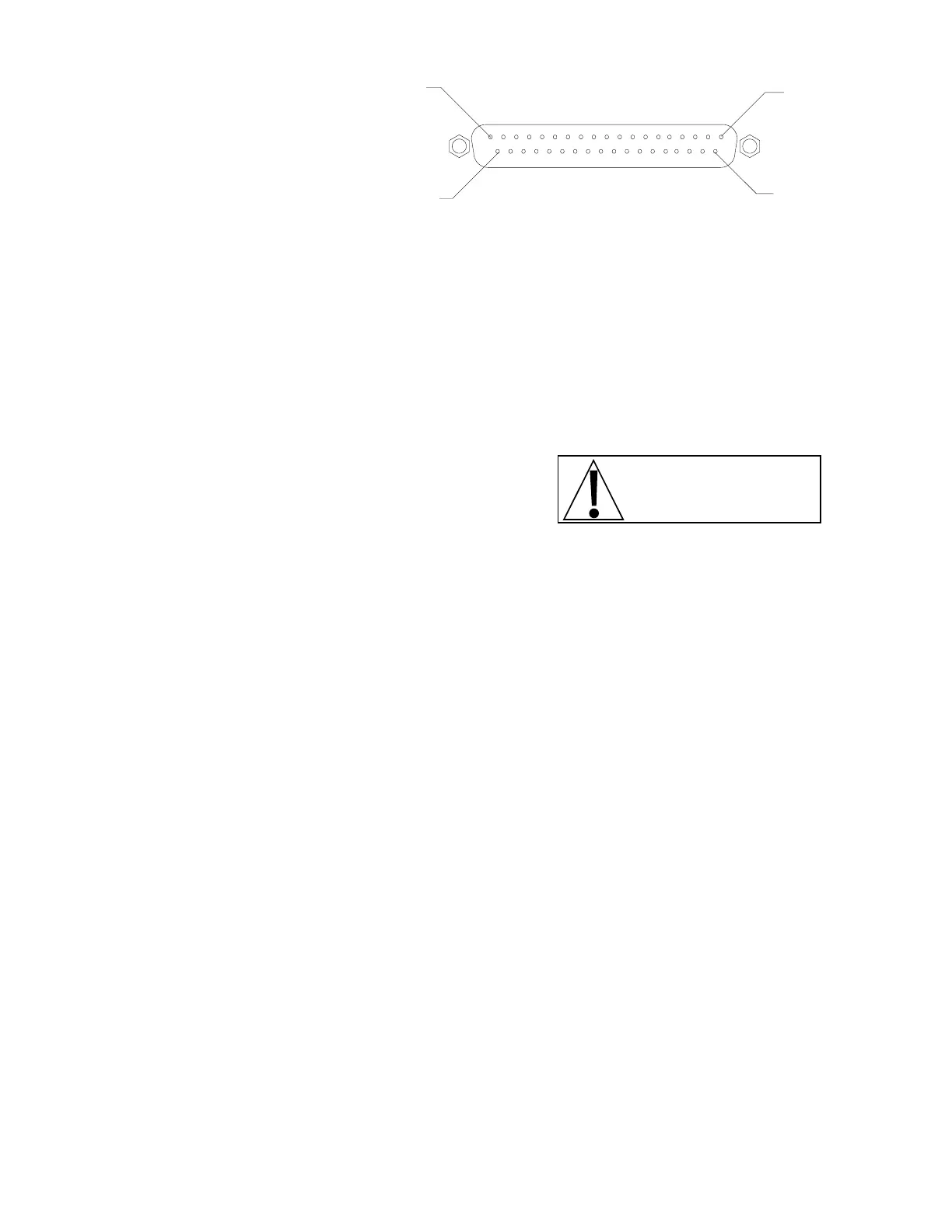
are via a 37-pin “D” connector. Refer
to figure no. 10 for the pin layout of
this connector.
PIN NO. FUNCTION PIN NO. FUNCTION PIN NO. FUNCTION
1 ............. ground 8 ................800 15 ....................... gross*/net
20 ............ ground 27 ...............400 34 ......................... aux. out
2 ...............800K 9 ................200 16 .......................... aux. in
21 ..............400K 28 ...............100 35 ........................ +polarity*
3 ...............200K 10 ................80 17 ........................ data valid
22 ..............100K 29 ................40 36 ........................over cap.*
4 ................80K 11 ................20 18 ............................ print
23 ...............40K 30 ................ 10 37 .......................input spec.
5 ................20K 12 .................8 19 ..... VCC out (200 OHM current limit)
24 ...............10K 31 .................4
6 .................8K 13 .................2
25 ................4K 32 .................1
7 .................2K 14 ............ motion
26 ................1K 33 ............. lb*/kg
PIN 19
PIN 37
PIN 1
PIN 20
figure no. 10 -
BCD output connector pin layout
NOTE! * indicates a high
level when function is true.
OPTICALLY ISOLATED INPUTS
Included with the I/O option are eight (8) programmable inputs that may be used to remotely (up to
100 feet) initiate various functions within the 748P. These inputs are accessed via a terminal block
on the back of the option board (see figure no. 9). Four (4) of the inputs are defined while the
remaining four (4) are available for special applications and will vary from application to application.
Of the four (4) that are defined, one is for Zero, another is for Tare, the third is for Print, and the
fourth is for Gross. Figure no. 9 illustrates the layout of this connector and identifies the inputs for
Zero, Tare, Print and Gross. Remember that the input must be connected to Gnd to initiate the
function.
PIN NUMBER FUNCTION
1 Gross
2 Print
3 Zero
4 Tare
5 Not used
6 Common
7 Not used
8 Not used
9 Not used
CALIBRATION OF THE ANALOG OUTPUT
The analog output has been calibrated at the factory and should require no other adjustment. If, for
some reason, it is found necessary or desirable to readjust this output, the procedure listed below
may be used. Note that in order to calibrate the analog output, it is first necessary to enter the
Calibration mode by gaining access to the calibration switch. Refer to the CALIBRATION section of
this manual for additional information. When the 748P senses that the optional I/O board is present,
it will cause the calibration sequence to include the steps necessary to calibrate the analog output.
The following describes that process:
 Loading...