3
P1
LOAD CELL
-Excitation
-Sense
-Signal
Shield
+Excitation
+Sense
+Signal
J3
J1
P11
J12 DOM/INT
Preset Weight
Comparator
Logic Level Output
P9
Printer
Output
Ground
RS232
20Ma
Bi-Directional
Serial Interface
P7
P5
Connector for
Option PC Board
Display Outline
P3
Power Input
Connector
PWC 2
PWC 3
PWC 4
PWC 5
PWC 1
Common
PWC 8
PWC 7
PWC 6
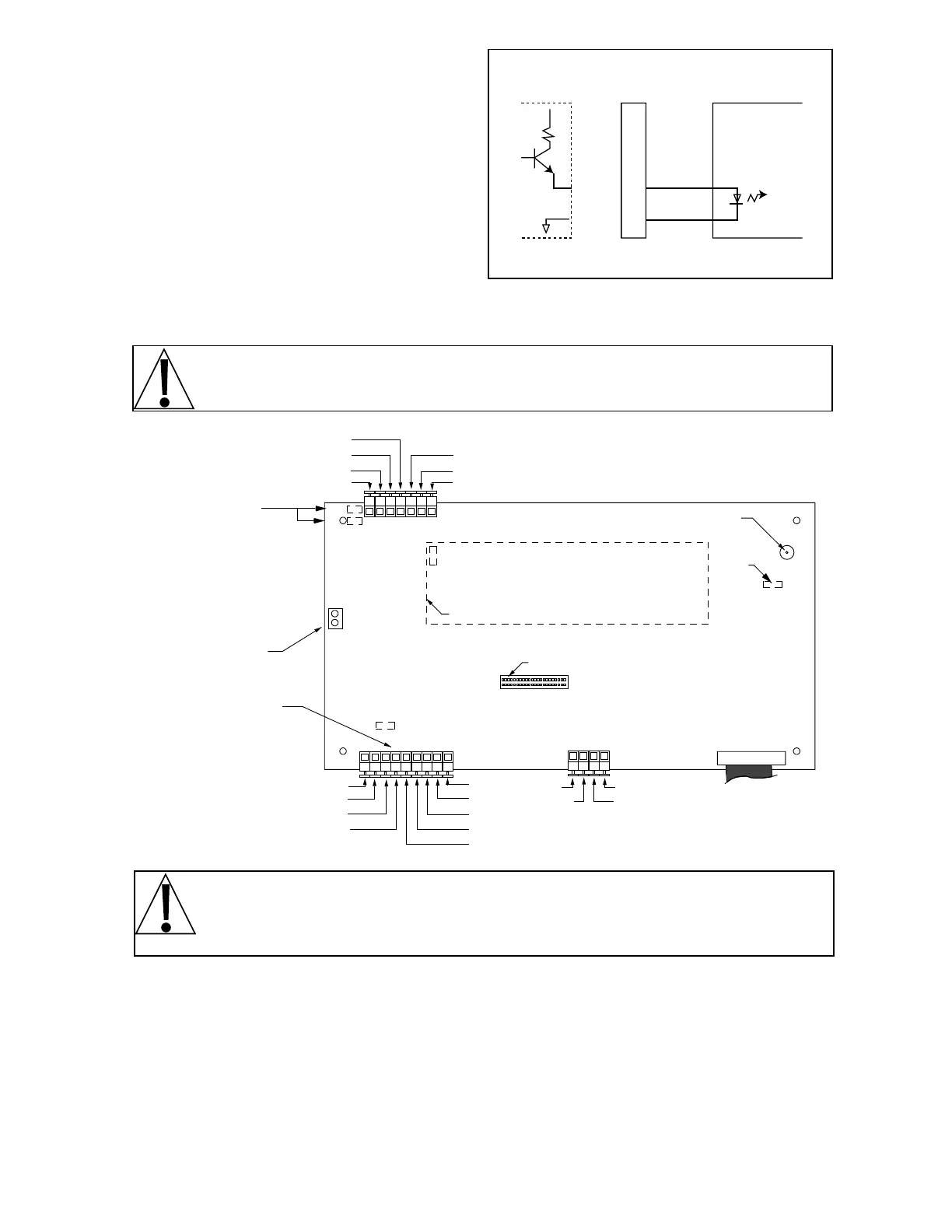
Sense/Excitations
Jumpers J1 and J3
Auto-On
Jumper
Calibration
Connector
CTS
figure no. 4
PC board layout
PRINTER CABLE INSTALLATION
Loosen the gland connector adjacent to the load
cell cable gland connector and slip the printer
cable through it and into the enclosure. Remove
2" of the outer insulating jacket from the cable,
then remove 1/4" of insulation from each of the
wires (refer to figure no.2). These wires are to be
connected to terminal block P9 at the bottom
edge of the printed circuit board. Refer to figure
no. 4 for the location of the terminal block.
Note that the printer output can be either RS232
compatible or 20mA current loop. To terminate
the wires, first press down the release bar on
the terminal. Slip the wire into the terminal
opening and release the bar to lock the wire in place.
NOTE! *RS232 CTS handshake input is enabled during calibration or setup review.
NOTE! After all terminations have been made, remove the excess cable from the
instrument enclosure and securely tighten each of the cable gland connectors. Do not
over-tighten these connectors but make certain they are snug. DO NOT USE TOOLS!
Tighten with fingers!
AUTO-ON
AUTO-ON jumper J7, when connected, will cause the indicator to power on automatically whenever
power is applied to the power input connector. If power is lost momentarily and then reapplied, the
indicator will turn on without pressing the ON key. See figure no. 4 for location.
DOMESTIC/INTERNATIONAL JUMPER (J12 DOM/INT)
Remove the jumper to comply with OIML requirements. The 748P will perform the following
functions: 1. A “lamp test” will be performed on power-up.
2. The printout of keyboard tare will be designated as “PT.”
3. The date format will be day/month/year.
Standard Printer Output Connector
20mA Current Loop Pin Definitions
(indicator has active end)
20mA 10 RX
GND 11
Internal
Circuitry
Printer
Conn.
Peripheral Device
Passive End
figure no. 3 - printer output connection
 Loading...