2
GIMBAL MOUNTING
The Model 748P Weight Indicating Instrument is housed in a NEMA 4X stainless steel wall or desk-
mount enclosure.
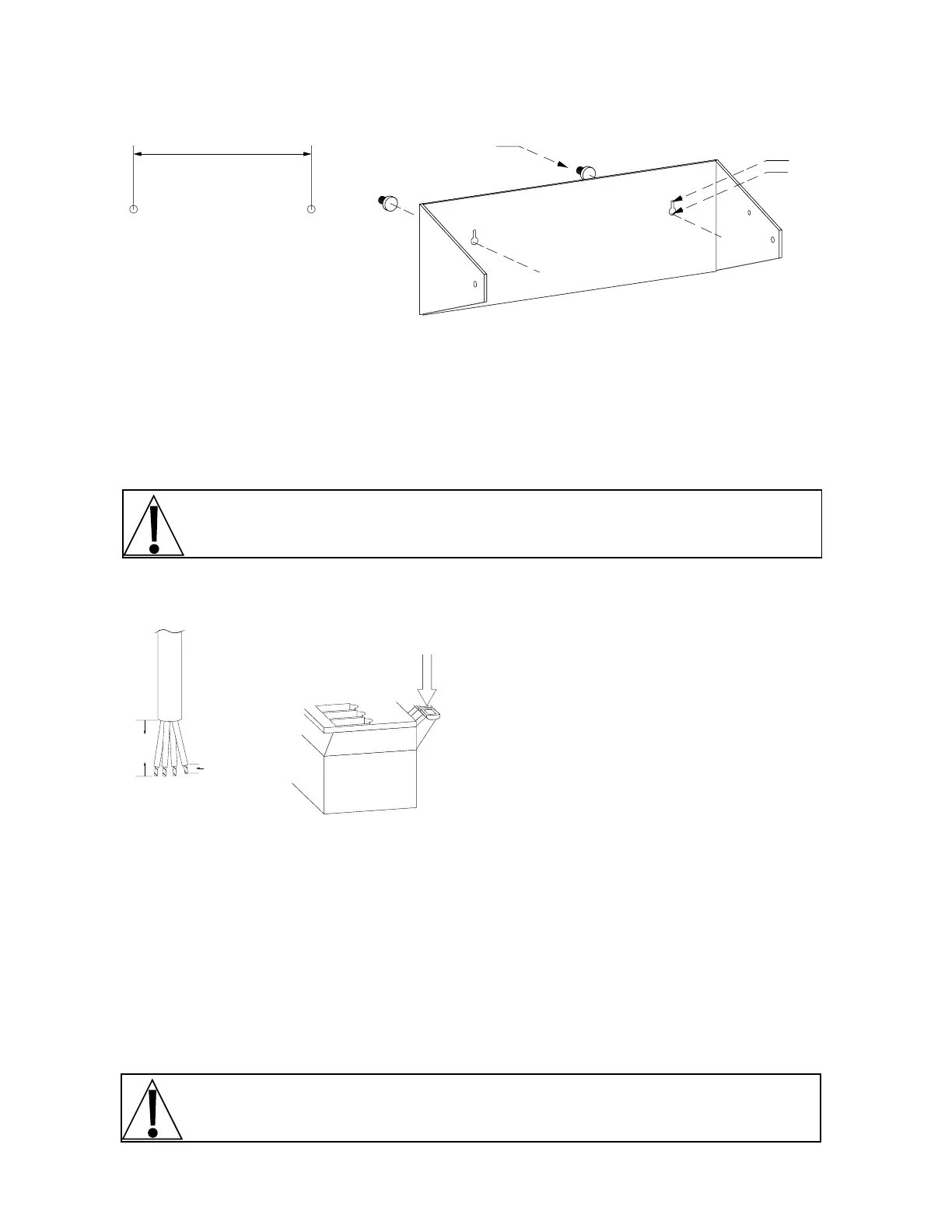
The 748P gimbal may be mounted on a desktop or other smooth, flat, horizontal surface or may be
mounted on a wall. Refer to figure no. 1 for a layout of wall-mounting bolts. If wall mounted, make
certain that the mounting surface is strong enough to support the instrument. The mounting location
should be where the display is easily viewed while being close enough to provide the operator easy
access to the keyboard. Carefully lay out the mounting hole locations, then drill and install the anchor
bolts. Attach the gimbal to the wall and securely tighten the retaining bolts.
LOAD CELL CONNECTION
CAUTION! Disconnect any external load cell power supply before connecting load cells to
the instrument. Failure to do so will result in permanent damage to the instrument.
Remove the ten (10) screws securing the back panel to the main housing, then loosen the cable
gland connector for the load cell. This gland connector is located on the rear panel of the enclosure.
Refer to figure no. 4 for an illustration of the connector layout.
Slip the single cable from the load cell or load cell
junction box through the gland connector and into
the enclosure. Remove 2" of the outer insulation
jacket then remove 1/4" of insulation from each of
the four (4) wires and shield without sense leads or
six (6) wires and shield with sense leads (refer to
figure no. 3). Connect each of the wires to terminal
block P1 as shown in figure no. 4. To terminate a
wire, first press down on the release bar for the
terminal, insert the wire into the terminal opening
then allow the release bar to return to its original
position, locking the wire in place. Repeat the
procedure until all of the wires are in place. NOTE! If the sense leads are NOT used, you must install
plug-in jumpers at J1 and J3 adjacent to the terminal block. These jumpers attach the sense leads to
the excitation leads. If sense leads ARE used (as in motor truck scales), these plug-in jumpers
should be positioned on one plug-in pin only or removed and stored for later use.
LOAD CELL CONNECTIONS WITH OVER 30 FEET OF CABLE
For installations with over 30 feet of cable between the indicator and the load cells, sense wires
should be used. The sense wires must be connected between the +SENS, -SENS terminals on the
indicator and the +EXCITATION, -EXCITATION wires of the load cells or the +SENS, -SENS
terminals of the load cell trim board or the section seal trim board. For the indicator to use the sense
wires, the +SENS jumper J1 and the -SENS jumper J3 must be open (see figure no. 4).
CAUTION! When in parallel runs, locate Load Cell cables a minimum of 24" away from all
AC wiring.
figure no. 1 - wall
mounting bolt layout
8.000"
Clearance for
#10 size screw
.203"
.375"
Terminal
2"
1/4"
figure no. 2 - terminal
block connections
 Loading...