44
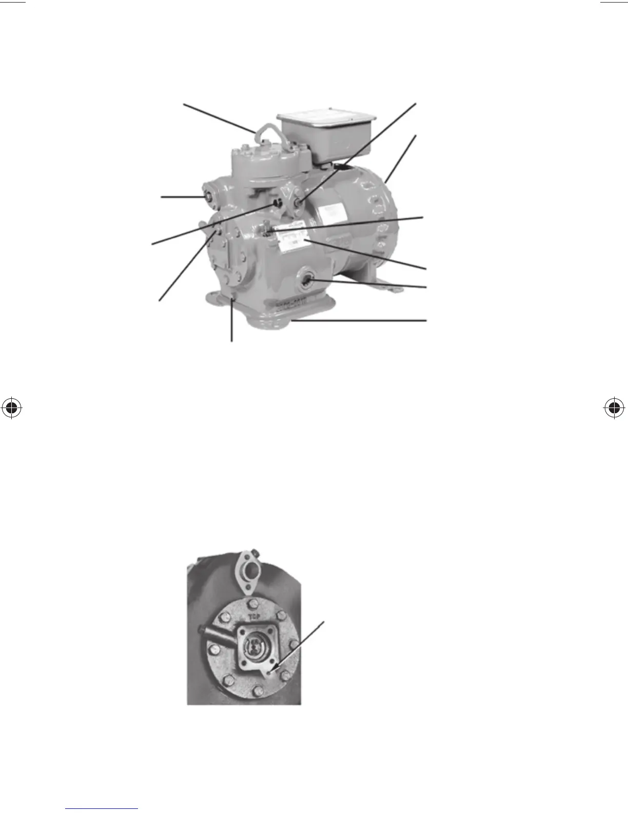
2.5 — Connection Points, 06D, 06E, and 06CC Compressors
NOTE: Bolt sizes and thread pitch: Compressors are built
using English unit bolts. The bolts have no exact metric
equivalents. Therefore, to prevent possible cross-threading,
loose bolts, or damage to threaded portions of the casing,
comparable metric measurements are not included.
LIFTING LUG
(NEW MODELS ONLY)
DISCHARGE VALVE
LOCATION
SINGLE PHASE MODELS
SUCTION VALVE LOCATED
AT MOTOR END
THREE PHASE MODELS
SUCTION VALVE
LOCATION
1/4" NPT HIGH
PRESSURE
CONNECTION
1/4" NPT PUMP
PRESSURE
(HIGH SIDE OIL
SAFETY SWITCH
CONNECTION)
7/16" - 20 SAE OIL DRAIN CONNECTION
(INSTALLED ON MODELS MANUFACTURED
AFTER 0100J----)
CRANKCASE HEATER
(ACCESSORY)
MOUNTS TO
UNDERSIDE OF
BOTTOM COVER
SIGHT GLASS
NAMEPLATE
1/4" NPT CONNECTION
USED FOR:
a) LOW PRESSURE
CONNECTION
b) LOW SIDE OIL
SAFETY SWITCH
CONNECTION
c) OIL FILL (SUMP)
CONNECTION
1/8" NPT
OIL PRESSURE TAP
OLD STYLE 06D
BEARING HEAD ASSEMBLY
Fig. 8 — 06D 2-Cylinder Compressor Connection Points
 Loading...


