61
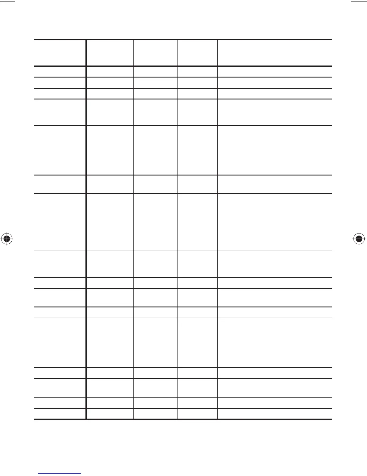
2.11 — Torque Guide - 06E and 06CC (50 to 99 Cfm)
Compressors
See Table 2.10 for Notes and Legend (page 60).
SIZE
DIAMETER
(in.)
THREADS
PER INCH
TORQUE
RANGE
(FT-LB)
TORQUE
RANGE
(NM)
USAGE
1/16 Pipe 8-12 11-16 Pipe plug crankshaft
1/8 Pipe 10-12 14-16 Orifice crankcase
No. 10 324-65-8 Oil pump drive segment
1/4 20
10-12
1.5-2.5
14-16
2-3
Con-rod cap screw
Motor lead set screw terminal
plate
1/4 28
3-5
4-6
12-15
12-15
12-15
12-15
4-7
5-8
16-20
16-20
16-20
16-20
Sight glass
Cylinder head gasket tab screw
Terminal box
Unloader valve
Discharge valve stop
Oil pump drive segment
5/16 18
16-20
20-25
22-27
27-34
Cover plate bearing head
Discharge service valve (4-cyl)
3/8 16
12
1
12
10-20
30-35
30-35
30-35
16
1
16
14-17
40-48
40-48
40-48
Terminal post jam nut #1*
Terminal post jam nut #2*
Terminal post jam nut #3*
Oil plug bearing head
Bottom plate, crankcase
Compressor foot
Terminal block
3/8 24-S
AE 8-12 11-16
P.E. Bearing head at 10 o’clock
position
NOTE: Not a field usable fitting
5/8 18-SAE 25-40 27-54 Access port under motor barrel
7/16 14
55-60
55-60
75-81
75-81
Motor end cover, crankcase
Bearing head, crankcase
7/16 20-SAE 8-12 11-16 Oil drain on bottom plate
1/2 13
80-90
80-90
80-90
85-100
85-100
85-100
109-122
109-122
109-122
115-136
115-136
115-136
Discharge service valve (6-cyl)
Interstate outlet (CC)
Suction service valve (1-5/8)
Interstage manifold (CC)
Suction manifold (CC)
Cylinder head
1/2 Pipe 30-40 40-54 Cylinder head sensor
5/8 11
25-3 0
90-100
34-40
122-136
Rotor lock crankshaft
Suction service valve (2-1/8)
3/4 16 50-60 68-81 Stator lock acorn nut
1-1/8 1830-40 40-54 Pressure relief valve
 Loading...


