30GT130-210, 230A-315A, and 330-420 Units — The field
power wiring enters the unit through the left side of the cooler
side power box. The control power enters the control box on
the compressor side of the unit.
NOTE: If optional non-fused disconnect is installed, power
wiring must enter through center panel of unit (disconnect
location).
IMPORTANT: Do not obstruct the field cooler con-
nections when installing field power into the power
box. Use 90-degree liquid-tight conduit fittings to con-
nect field power to the unit and avoid the cooler pip-
ing area.
All units have a single location for power connection
(one per module on 230-420 units) to simplify field power
wiring. The maximum acceptable wire size for the terminal
block is 500 kcmil. Copper, copper-clad aluminum, or alu-
minum conductors are acceptable for all units except 30GT210,
315A, 390A, and 420A/B 208/230-3-60 units. These units
require copper conductors. For 208/230-3-60 and 230-3-50
units, 9 parallel conductors are required. All other voltages
require 6 parallel conductors.
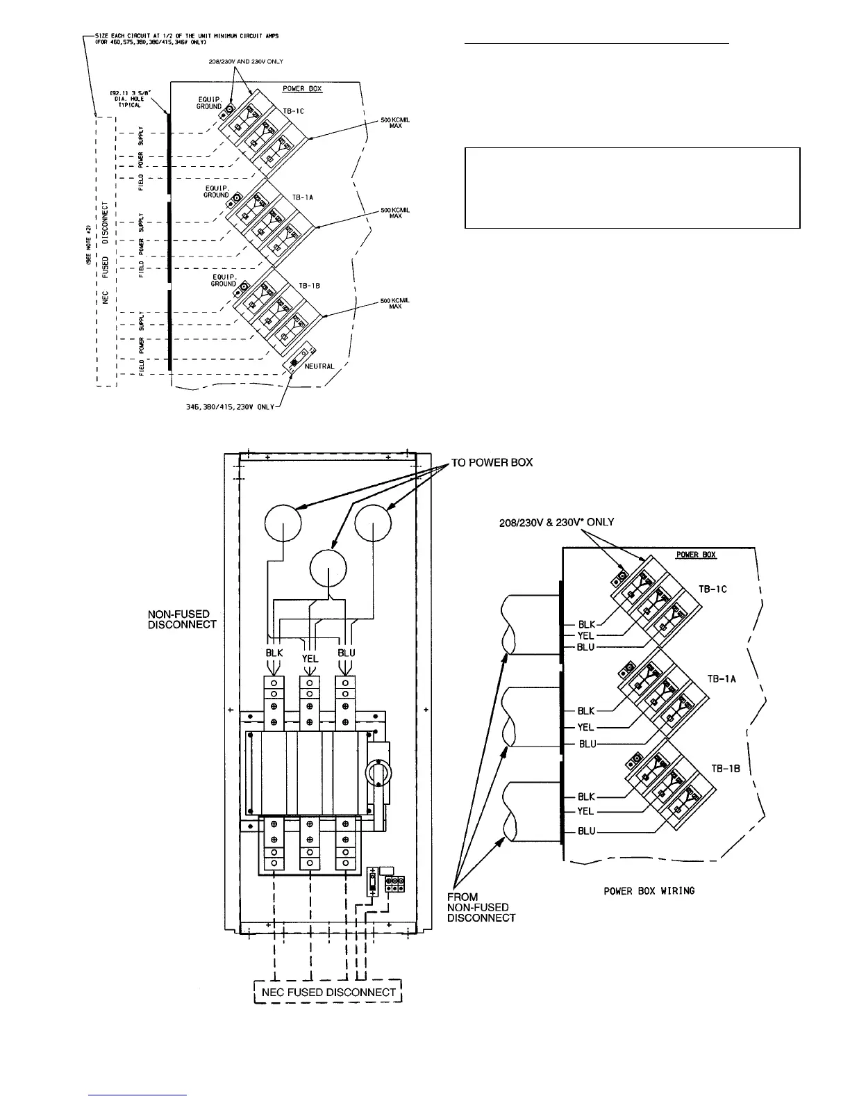
Fig. 12 — Field Power Wiring; Unit Sizes 130-210
*130-210 and 330A/B-420A/B units only.
NOTE: See Fig. 5 for location of non-fused disconnect on unit.
Fig. 13 — Field Power Wiring; Unit Sizes 130-210,230A-315A,330A/B-420A/B with
Non-Fused Disconnect Option
29
 Loading...