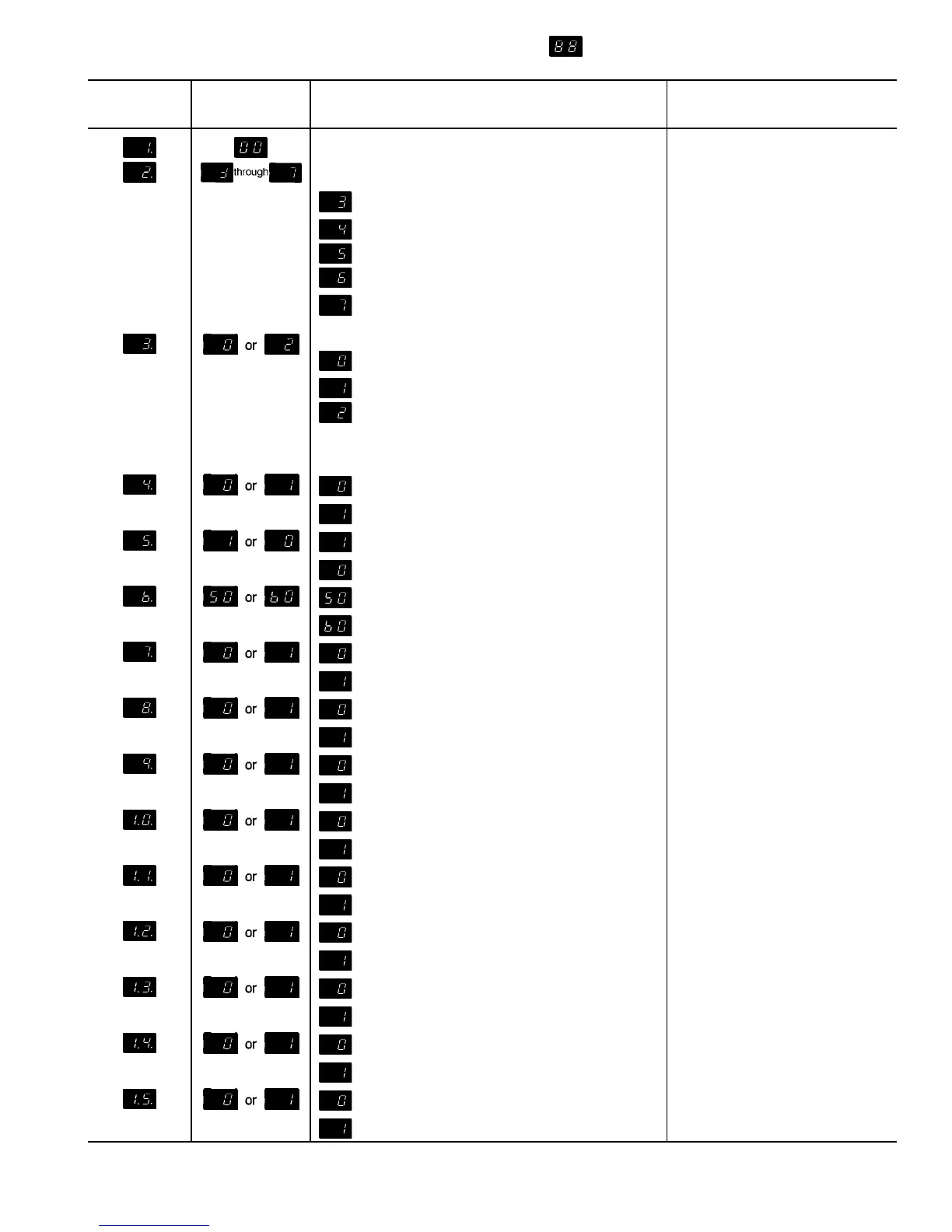
Table 8 — Quick Test
SECTION A. — Configuration and Switch Check
QUICK TEST
STEP NO.
NORMAL
DISPLAY
STEP DESCRIPTION
HEADER POSITON
OR
CONTROL SWITCH
Type Unit — Air-Cooled Chiller Configuration Header: 1 and 2
No. of Compressors Configuration Header: 3, 4, and 5
= 080, 230B
= 090-110, 130 (60 Hz), 245B-315B
= 130 (50 Hz), 150, 230A-255A
= 170, 190, 270A, 290A, 330A/B, 360A/B, 390B
= 210, 315A, 390A, 420A/B
No. of Unloaders
= Switch 6 Off, Switch 7 Off
DIP Switches 6 and 7
= Switch 6 On, Switch 7 Off
= Switch 6 Off, Switch 7 On
NOTE: There are no unloaders on 190, 210 and
associated modular units.
= Water
DIP Switch 8
= Brine*
= EXV
Configuration Header: 6
= TXV
=50Hz
Configuration Header: 7
=60Hz
= External Reset
DIP Switch 1
= Return Fluid Reset
= Reset Disabled
DIP Switch 2
= Reset Enabled
= Pulldown Disabled
DIP Switch 3
= Pulldown Enabled
= Demand Limit Disabled
DIP Switch 5
= Demand Limit Enabled
= Remote On/Off — Switch/Jumper Open
TB6-3 and TB6-4
= Remote On/Off — Switch/Jumper Closed
= Loss-of-Charge Switch A Open
Circuit A Loss-of-Charge
Switch
= Loss-of-Charge Switch A Closed
= Loss-of-Charge Switch B Open
Circuit B Loss-of-Charge
Switch
= Loss-of-Charge Switch B Closed
= Low Oil Pressure Switch A Open
Circuit A Low Oil Pressure
Switch
= Low Oil Pressure Switch A Closed
= Low Oil Pressure Switch B Open
Circuit B Low Oil Pressure
Switch
= Low Oil Pressure Switch B Closed
See legend and notes on page 49.
47
 Loading...