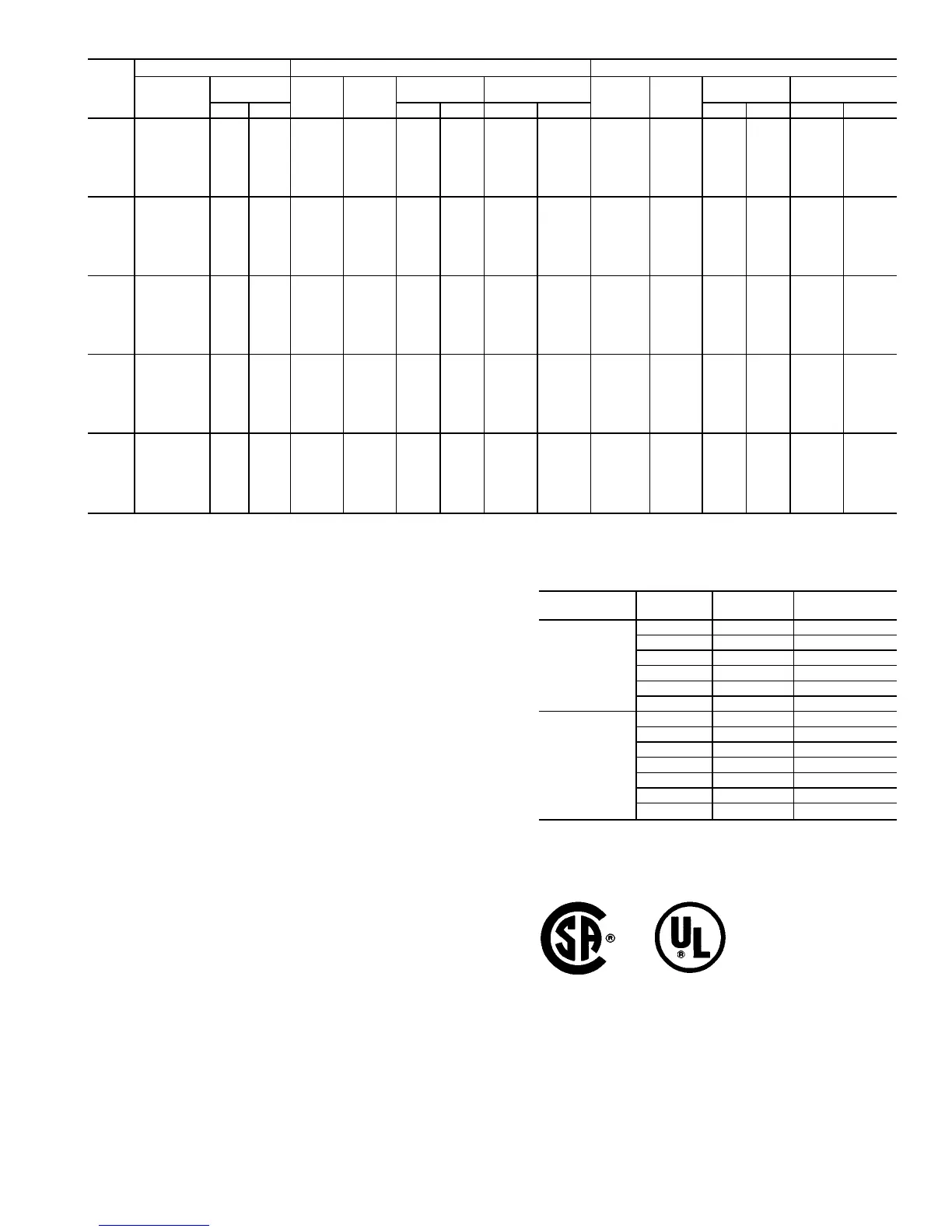
Table 4B — Unit Electrical Data, 30GT130-210
30GT
UNIT
SIZE
VOLTAGE STANDARD CONDENSER FAN HIGH STATIC CONDENSER FAN
Nameplate
V-Hz
(3 Phase)
Supplied*
MCA MOCP
Rec
Fuse Size
ICF
MCA MOCP
Rec
Fuse Size
ICF
Min Max XL PW XL PW XL PW XL PW
130
208/230-60 187 253 610.2 700 700 700 1111.1 835.1 701.8 800 800 800 1202.7 926.7
460-60 414 506 271.8† 300 300 300 534.1 397.0 303.8 350 350 350 567.0 429.0
575-60 518 633 245.9 300 300 300 350.5 318.5 263.9 300 300 300 368.5 336.5
380-60 342 418 331.1 400 400 400 612.8 460.8 366.1 400 400 400 647.8 495.8
230-50 207 253 559.1 600 600 600 969.5 751.5 617.1 700 700 700 1027.5 809.5
346-50 325 380 382.9 450 400 400 682.6 522.6 425.9 500 450 450 725.6 565.6
380/415-50 342 440 338.6† 350 350 350 583.0 463.7 377.6† 400 400 400 622.0 502.7
150
208/230-60 187 253 664.2 800 800 800 1165.1 889.1 755.8 800 800 800 1256.7 980.7
460-60 414 506 312.9 350 350 350 576.1 438.1 334.9 400 400 400 608.1 470.1
575-60 518 633 272.3 300 300 300 440.9 344.9 290.3 350 350 350 458.9 362.9
380-60 342 418 359.9 400 400 400 641.6 489.6 394.9 450 450 450 676.6 524.6
230-50 207 253 629.4 700 700 700 1039.8 821.8 629.4 700 800 800 1039.8 879.8
346-50 325 380 465.1 500 450 450 764.8 604.8 508.1 600 500 500 807.8 647.8
380/415-50 342 440 377.9 400 400 400 641.0 503.0 416.9 450 450 450 680.0 542.0
170
208/230-60 187 253 727.5 800 800 800 1098.9 896.9 819.1 1000 1000 1000 1190.5 988.5
460-60 414 506 323.6 350 350 350 518.0 417.0 355.5 400 400 400 550.0 449.0
575-60 518 633 294.6 300 350 350 418.5 348.5 312.6 350 350 350 436.5 366.5
380-60 342 418 387.8 400 450 450 598.0 486.0 422.8 450 450 450 633.0 521.0
230-50 207 253 677.7 700 800 800 1088.1 870.1 735.7 800 800 800 1146.1 928.1
346-50 325 380 472.1 500 500 500 771.8 611.8 515.1 600 600 600 814.8 654.8
380/415-50 342 440 387.3 450 450 450 650.4 512.4 426.3 450 450 450 689.4 551.4
190
208/230-60 187 253 800.0 800 1000 1000 1301.5 1025.5 910.6 1000 1000 1000 1411.5 1135.5
460-60 414 506 368.2 400 400 400 631.4 493.4 406.2 450 450 450 669.4 531.4
575-60 518 633 325.9 350 350 350 494.5 398.5 347.5 400 400 400 516.1 420.1
380-60 342 418 432.5 500 450 450 714.2 562.2 474.5 500 500 500 756.2 604.2
230-50 207 253 749.9 800 800 800 1160.3 942.3 819.5 700 1000 1000 1229.9 1011.9
346-50 325 380 554.1 600 600 600 853.8 693.8 605.7 1000 700 700 905.4 745.4
380/415-50 342 440 515.7 500 500 500 669.4 575.3 497.0 500 600 600 760.1 622.1
210
208/230-60 187 253 890.4 1000 1000 1000 1391.3 1115.3 1000.0 1000 1200 1200 1501.3 1225.3
460-60 414 506 413.1 450 450 450 676.3 538.3 451.1 500 500 500 714.3 576.3
575-60 518 633 362.5 400 400 400 531.1 435.1 384.1 400 400 400 552.7 456.7
380-60 342 418 479.3 500 500 500 761.0 609.0 521.3 600 600 600 803.0 651.0
230-50 207 253 796.2 800 800 800 1206.6 988.3 865.8 1000 800 800 1276.2 1058.2
346-50 325 380 567.5 600 600 600 867.2 707.2 619.1 700 700 700 918.8 758.8
380/415-50 342 440 474.5 500 500 500 737.6 599.6 521.3 600 600 600 784.4 646.4
LEGEND AND NOTES FOR TABLES 4A to 7
LEGEND
FLA — Full Load Amps (Fan Motors)
ICF — Maximum Instantaneous Current Flow during starting (the
point in the starting sequence where the sum of the LRA for
the starting compressor, plus the total RLA for all running
compressors, plus the total FLA for all running fan motors is
maximum)
kW — Total condenser fan motor power input
LRA — Locked Rotor Amps
MCA — Minimum CircuitAmps (for wire sizing) — complies with NEC
Section 430-24
MOCP — Maximum Overcurrent Protective Device Amps
NEC — National Electrical Code, U.S.A.
Rec Fuse
Size
— Recommended dual-element fuse amps; 150% of largest com-
pressor RLAplus 100% of sum of remaining compressor RLAs.
Size up to the next larger standard fuse size.
PW — Part Wind
RLA — Rated Load Amps (Compressors)
XL — Across-the-Line
*Units are suitable for use on electrical systems where voltage supplied to the
unit terminals is not below or above the listed minimum and maximum limits.
Maximum allowable phase imbalance is: voltage, 2%; amps, 10%.
†Wherever XL and PW data differ, the higher value of the two is listed.
**130-210 and 330A/B-420A/B units only.
NOTES:
1. All modules have single point primary power connection. (Each module re-
quires its own power supply.) Main power must be supplied from a field-
supplied disconnect.
2. The unit control circuit power (115 v, single-phase for 208/230-, 460-, and
575-v units; 230 v, single-phase for all other voltages) must be supplied
from a separate source through a field-supplied disconnect. The control
circuit transformer accessory may be applied to power from primary unit
power.
3. Crankcase and cooler heaters are wired into the control circuit so they are
always operable as long as the control circuit power supply disconnect is
on, even if any safety device is open, and the unit ON/OFF switch is in the
OFF position.
4. Units have the following power wiring terminal blocks and parallel
conductors:
30GT
UNIT SIZE
VOLTAGE
TERMINAL
BLOCKS
PARALLEL
CONDUCTORS
080 to 110,
230B to 315B
208/230 1 6
460 1 3
575 1 3
380 1 3
346 1 3
380/415 1 3
130 to 210,
230A to 315A,
330A/B to
420A/B
208/230 3 9
460 2 6
575 2 6
380 2 6
230** 3 9
346 2 6
380/415 2 6
5. Maximum incoming wire size for each terminal block is 500 kcmil.
6. Power draw of control circuits includes both crankcase heaters and cooler
heaters (where used). Each compressor has a crankcase heater which draws
180 w of power.
Units ordered with cooler heater option have 8 cooler heaters, 210 w each.
33
 Loading...