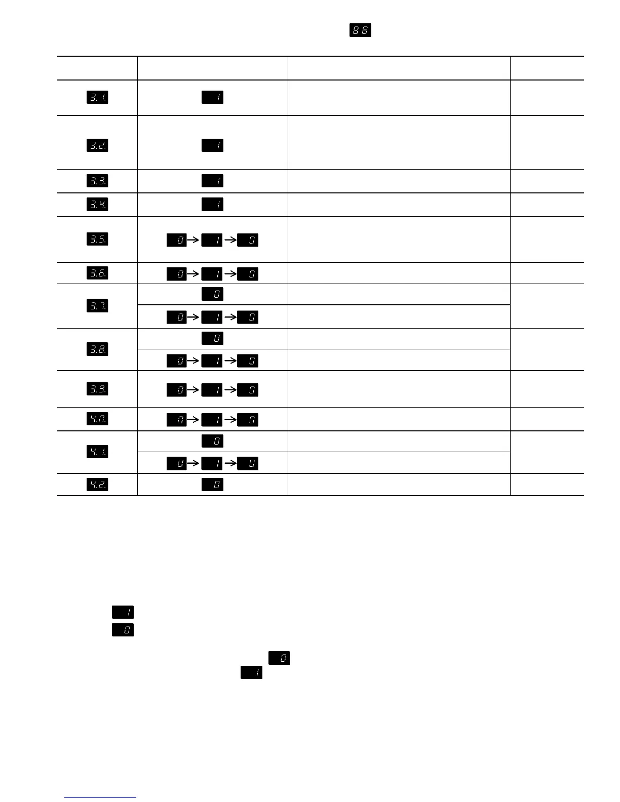
Table 8 — Quick Test (cont)
SECTION C. — Output Relay Check
QUICK TEST
STEP NO.
NORMAL
DISPLAY
STEP DESCRIPTION RELAY NO.
Energize First Stage of Condenser Fans
080-110** — OFM3, OFM4
130-210** — OFM3, OFM4, OFM9, OFM10
K11
Energize Second Stage of Condenser Fans
080, 090** — OFM5, OFM6
100, 110** — OFM5, OFM6, OFM7, OFM8
130-170** — OFM1, OFM2
190, 210** — OFM1, OFM2, OFM11, OFM12
K12
Energize Liquid Line Solenoid Valve
(080-110, TXV only), Circuit A
K9
Energize Liquid Line Solenoid Valve
(080-110, TXV only), Circuit B
K10
††
Energize Compressor A1 and OFM1
(008-110**)
Energize Compressor A1, OFM5, and OFM7
(all other unit sizes)
K1
††
Energize Compressor A2 K2
No Action (080-110, 130 [60 Hz]**)
K3
††
Energize Compressor A3 (130 [50 Hz],
150-210**)
Energize Unloader A1 (080-170**)
K4
††
Energize Compressor A4 (210**)
††
Energize Compressor B1, OFM2 (080-110**)
Energize Compressor B1, OFM6, and OFM8
(all other unit sizes)
K5
††
No Action (080**)
Energize Compressor B2 (all other unit sizes)
K6
No Action (080-150**)
K7
††
Energize Compressor B3 (170-210)
Energize Unloader B1 (080-170)
No Action (190-210**)
K8
LEGEND
CPCS — Compressor Protection Control System
CR — Control Relay
DIP — Dual, In-Line Package
EXV — Electronic Expansion Valve
FIOP — Factory-Installed Option
OFM — Outdoor (Condenser) Fan Motor
TB — Terminal Block
TXV — Thermostatic Expansion Valve
*Do not change select switch to brine on units that do not have modifications for brine.
Special modifications are required. Contact Carrier for details.
†Display is for Flotronic™ EXV units only.
Display is for 080-110 Flotronic FIOP units (with TXV).
**And associated modular units.
††Compressors will be energized for 10 seconds. indicates open CPCS or CR
module contacts (compressor energized). indicates closed CPCS or CR con-
tacts (compressor deenergized).
49
 Loading...