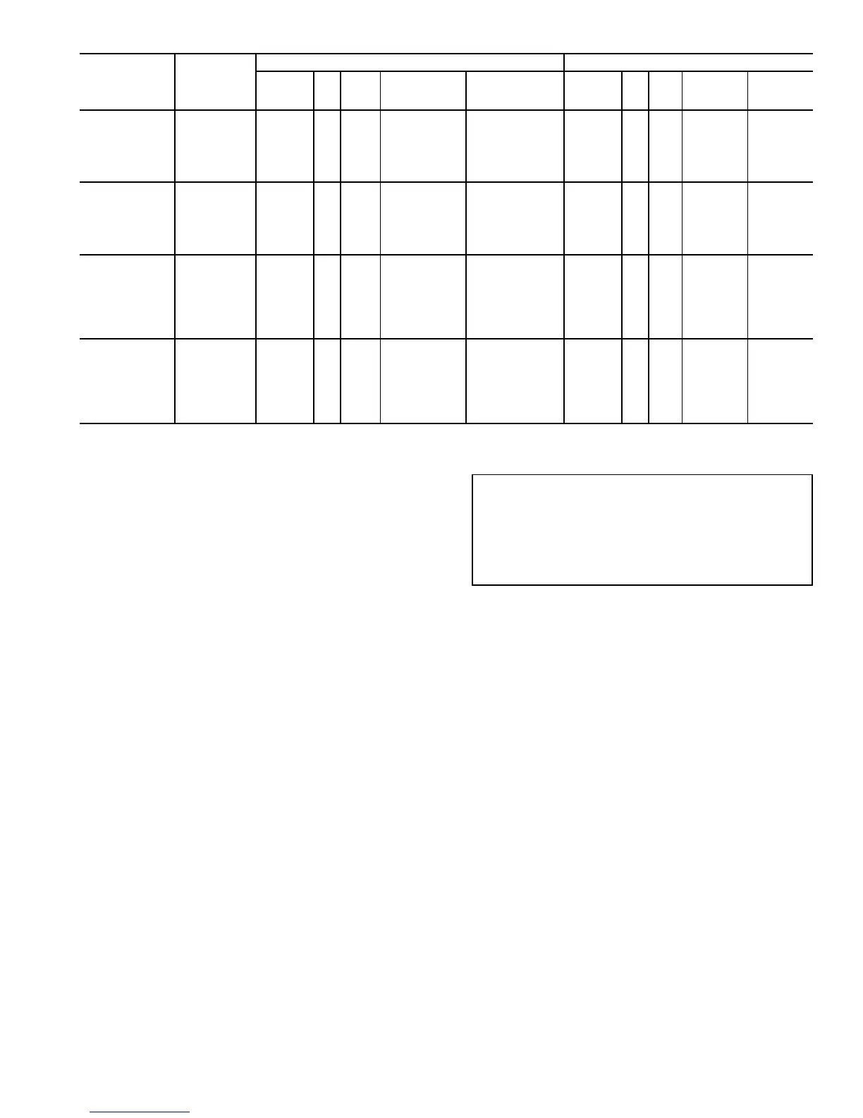
Table 7 — Condenser Fan Electrical Data
30GT
UNIT SIZE
NAMEPLATE
VOLTAGE
(V-Ph-Hz)
STANDARD/LOW NOISE CONDENSER FANS HIGH STATIC CONDENSER FANS
Total
Quantity
Hp kW
(Quantity)
FLA
(ea)
(Quantity)
LRA
(ea)
Total
Quantity
Hp kW
(Quantity)
FLA
(ea)
(Quantity)
LRA
(ea)
080,090,
230B,245B
208/230-3-60
6 1 0.746
(4) 6.6, (2) 5.5 (4) 31.6, (2) 30.0
6 5 3.73
(6) 14.6 (6) 41.6
460-3-60 (4) 3.3, (2) 2.8 (4) 31.6, (2) 30.0 (6) 6.3 (6) 41.6
575-3-60 (6) 3.4 (6) 30.0 (6) 5.2 (6) 42.0
380-3-60 (6) 3.9 (6) 20.9 (6) 7.4 (6) 54.0
346-3-50 (6) 4.4 (6) 20.9 (6) 8.7 (6) 53.0
380/415-3-50 (6) 3.4 (6) 30.0 (6) 7.3 (6) 41.0
100,110,
255B,270B,
290B,315B
208/230-3-60
8 1 0.746
(6) 6,6, (2) 5.5 (6) 31.6, (2) 30.0
8 5 3.73
(8) 14.6 (8) 41.6
460-3-60 (6) 3.3, (2) 2.8 (6) 31.6, (2) 30.0 (8) 6.3 (8) 41.6
575-3-60 (8) 3.4 (8) 30.0 (8) 5.2 (8) 42.0
380-3-60 (8) 3.9 (8) 20.9 (8) 7.4 (8) 54.0
346-3-50 (8) 4.4 (8) 20.9 (8) 8.7 (8) 53.0
380/415-3-50 (8) 3.4 (8) 30.0 (8) 7.3 (8) 41.0
130-170
230A-270A,
330A/B,360B
(50 Hz)
208/230-3-60
10 1 0.746
(6) 6.6, (4) 5.5 (6) 31.6, (4) 30.0
10 5 3.73
(10) 14.6 (10) 41.6
460-3-60 (6) 3.3, (4) 2.8 (6) 31.6, (4) 30.0 (10) 6.3 (10) 41.6
575-3-60 (10) 3.4 (10) 30.0 (10) 5.2 (10) 42.0
380-3-60 (10) 3.9 (10) 20.9 (10) 7.4 (10) 54.0
346-3-50 (10) 4.4 (10) 20.9 (10) 8.7 (10) 53.0
230-3-50** (10) 6.4 (10) 30.3 (10) 12.2 (10) 41.6
380/415-3-50 (10) 3.4 (10) 30.0 (10) 7.3 (10) 41.0
190,210,
290A,315A,
360A/B (60 Hz),
360A (50 Hz),
390A/B,420A/B
208/230-3-60
12 1 0.746
(8) 6.6, (4) 5.5 (8) 31.6, (4) 30.0
12 5 3.73
(12) 14.6 (12) 41.6
460-3-60 (8) 3.3, (4) 2.8 (8) 31.6, (4) 30.0 (12) 6.3 (12) 41.6
575-3-60 (12) 3.4 (12) 30.0 (12) 5.2 (12) 42.0
380-3-60 (12) 3.9 (12) 20.9 (12) 7.4 (12) 54.0
346-3-50 (12) 4.4 (12) 20.9 (12) 8.7 (12) 53.0
230-3-50 (12) 6.4 (12) 30.3 (12) 12.2 (12) 41.6
380/415-3-50 (12) 3.4 (12) 30.0 (12) 7.3 (12) 41.0
Step 6 — Install Accessories
ELECTRICAL—Anumber of electrical accessories are avail-
able to provide the following optional features (for details,
refer to the Controls and Troubleshooting book):
• Accessory temperature reset board and accessory ther-
mistor (used for any of the following types of temperature
reset):
— Return fluid temperature reset
— Space temperature reset (requires accessory
thermistor)
— Outdoor air temperature reset (requires accessory
thermistor)
• Chilled fluid flow switch
LOW-AMBIENT OPERATION — If operating tem-
eratures below 0° F (−18 C) are expected, refer to sep-
rate installation instructions for low-ambient operation,
Motormastert III control.
HOT GAS BYPASS — Hot gas bypass usually is not rec-
ommended because it results in application of equipment out
of its normal design application range. However, if its use is
required, the appropriate hot gas bypass package may be used.
For installation details, refer to separate instructions sup-
plied with the accessory package.
MISCELLANEOUSACCESSORIES — For applications re-
quiring special accessories, the following packages are avail-
able: condenser hail guard, gage panel, sound reduction kit,
convenience outlet, and security grille package.
PRE-START-UP
IMPORTANT: Before beginning Pre-Start-Up or
Start-Up, complete Start-Up Checklist for Flotronic™
Chiller Systems at center of this publication
(page CL-1). The Checklist assures proper start-up of
a unit, and provides a record of unit condition, appli-
cation requirements, system information, and opera-
tion at initial start-up.
Do not attempt to start the chiller until following checks
have been completed.
System Check
1. Check all auxiliary components, such as the chilled fluid
circulating pump, air-handling equipment, or other equip-
ment to which the chiller supplies liquid. Consult manu-
facturer’s instructions. If the unit has field-installed ac-
cessories, be sure all are properly installed and wired
correctly. Refer to unit wiring diagrams.
2. Backseat (open) compressor suction and discharge shut-
off valves. Close valves one turn to allow refrigerant pres-
sure to reach the test gages.
3. Open liquid line service valves.
4. Fill the chiller fluid circuit with clean water (with
recommended inhibitor added) or other noncorrosive
fluid to be cooled. Bleed all air out of high points of
system. An air vent is included with the cooler. If
43
 Loading...